background image

12

Front & Rear Panels

—Continued

k

Audio input indicators (76, 120)

Indicate the type of audio input that’s selected as the 
audio source: HDMI, ANALOG, or DIGITAL. 

While a digital HD Radio transmission is being 
received, the DIGITAL indicator lights up. While an 
analog HD Radio transmission is being received, 
the ANALOG indicator lights up.

l

Volume level (70)

Displays the volume level.

m

MUTING indicator (71)

Flashes while the AV receiver is muted.
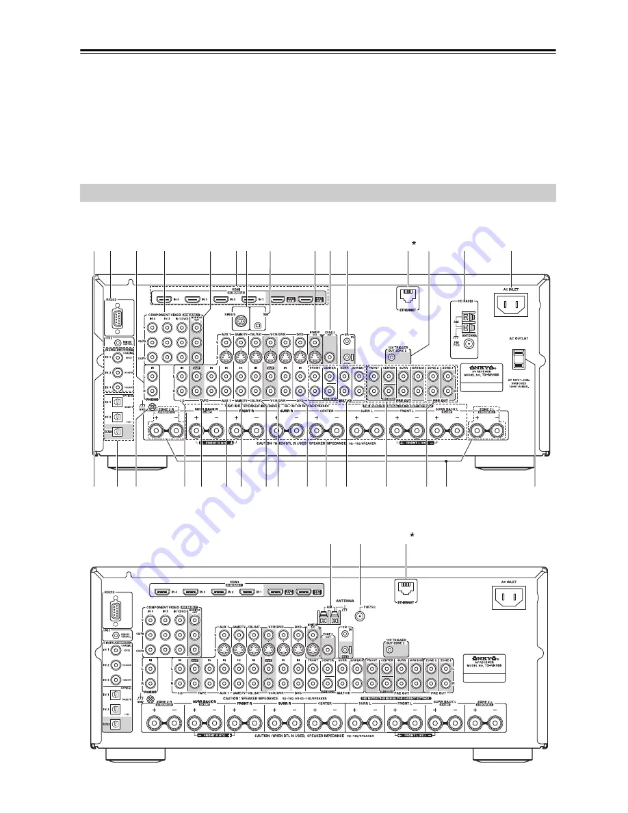
Rear Panel

bt ck

8

5

4

9

bq

bo bp

dn

2

1

br

bs

3

67

bl bn

cm

cn co

cq

cr

dk

dl dm

cs ct

cp

cl

1

*1

TX-NR906 only

North American model

bk

bm

bo

1

Other models

Summary of Contents for TX NR906 - AV Network Receiver

Page 1: ...g the instructions in this manual will enable you to obtain optimum performance and listening enjoyment from your new AV Receiver Please retain this manual for future reference Contents Introduction 2...

Page 2: ...aratus does not operate normally by following the operating instructions Adjust only those controls that are covered by the operating instructions as an improper adjustment of other controls may resul...

Page 3: ...eave rubber or plastic items on this unit for a long time because they may leave marks on the case This unit s top and rear panels may get warm after prolonged use This is normal If you do not use thi...

Page 4: ...which is marked with the letter L or coloured red IMPORTANT The plug is fitted with an appropriate fuse If the fuse needs to be replaced the replacement fuse must approved by ASTA or BSI to BS1362 an...

Page 5: ...mat Setup not North American models 62 AM Frequency Step Setup on some models 63 Changing the Input Display 63 Automatic Speaker Setup Audyssey MultEQ XT 64 Basic Operations 70 Selecting the Input Sou...

Page 6: ...dels Audyssey MultEQ XT 12 to Correct Room Acoustic Problems Audyssey Dynamic EQ 12 Loudness Correction Audyssey Dynamic Volume 12 Indepedent Crossover Adjustment 40 50 60 70 80 90 100 120 150 200 Hz...

Page 7: ...ied Accessories Make sure you have the following accessories In catalogs and on packaging the letter at the end of the product name indicates the color Specifications and operation are the same regard...

Page 8: ...eakers for serious music listening in main room see page 23 Can be used with the subwoofer center surround or surround back speakers as required see page 98 Zone 2 Enjoy 2 channel stereo playback and...

Page 9: ...y See Display on page 11 g DISPLAY button 72 Displays various information about the currently selected input source h MASTER VOLUME control 70 and indicator Sets the volume of the AV receiver to dB 81...

Page 10: ...n 73 Selects the Auto or Manual tuning mode v SETUP button This button is used to access the onscreen setup menus that appear on the connected TV w TUNING PRESET Arrow and ENTER buttons When the AM or...

Page 11: ...d ZONE 2 indicator 134 Lights up when Powered Zone 2 is being used e Listening mode and format indicators 81 Show the selected listening mode and audio input signal format f Tuning indicators 73 HD N...

Page 12: ...being received the DIGITAL indicator lights up While an analog HD Radio transmission is being received the ANALOG indicator lights up l Volume level 70 Displays the volume level m MUTING indicator 71...

Page 13: ...ted to a video input on a TV in Zone 2 l FM ANTENNA not North American model This jack is for connecting an FM antenna m IR IN OUT A commercially available IR receiver can be con nected to the IR IN j...

Page 14: ...rs respectively or used to bi amp or bridge front Speakers A See Bi amping Front Speakers A on page 27 and Bridging Front Speakers A on page 28 ct MULTI CH input FRONT L R CENTER SUBWOOFER SURR L R an...

Page 15: ...the same type is used in the same room or the AV receiver is installed close to equipment that uses infrared rays the remote control ler may not work reliably Don t put anything on top of the remote c...

Page 16: ...enter the appropriate remote control code first see page 137 ZONE 2 ZONE 3 Modes These modes are for controlling Zone 2 and Zone 3 see page 133 RECEIVER TAPE mode is used to control the AV receiver I...

Page 17: ...button the REMOTE MODE button for the currently selected mode lights up o SLEEP button 72 Used with the Sleep function p VOL q w button 70 Adjusts the volume of the AV receiver regardless of the curre...

Page 18: ...tal or DTS l OPEN CLOSE 0 button Opens and closes the disc tray m CLEAR button Cancels functions and clears entered numbers n MENU button Displays a DVD s menu o RETURN button Exits the DVD player s o...

Page 19: ...everse Pause Stop and Fast Forward h REC y button Starts recording i REPEAT button Used with the repeat playback function j OPEN CLOSE 0 button Opens or closes the disc tray or ejects the MiniDisc k C...

Page 20: ...previous or next playlist on the iPod k REPEAT button Used with the repeat function l MENU button Used to access menus m Play 1 button Starts playback If the component is off it will turn on automati...

Page 21: ...server or USB mass storage device h RETURN button Returns to the previous display i Play 1 button Starts playback j Next 6 button Selects the next song k Stop 2 button Stops playback l RANDOM button...

Page 22: ...m the listener Center speaker This speaker enhances the front left and right speakers making sound movements distinct and providing a full sound image For movies it s used mainly for dialog Position i...

Page 23: ...uration can be selected at a time The versatility offered by the Speakers A and Speakers B configurations means you can configure the AV receiver to suit your exact requirements and application Two ty...

Page 24: ...nput on your powered sub woofer If your subwoofer is unpowered and you re using an external amplifier connect the PRE OUT SUBWOOFER to the amp s input Attaching the Speaker Labels The AV receiver s po...

Page 25: ...peakers Pay close attention to speaker wiring polarity Connect positive terminals to only positive terminals and negative terminals to only negative termi nals If you get them the wrong way around the...

Page 26: ...otes When Speakers A is selected the front left speaker A and front right speaker A become the main front speakers When Speakers B is selected the front left speaker B and front right speaker B become...

Page 27: ...eter high and woofer low terminals Bi amping can only be used with speakers that support bi amping Refer to your speaker manual Bi amping Speaker Hookup Bi amping Front Speakers A 1 Connect the AV rec...

Page 28: ...ront Speaker A setting to BTL to enable bridging see page 61 When front Speakers A are bridged front Speakers B must be wired normally or not used Notes Use only front speakers with an impedance of 8...

Page 29: ...gh and woofer low terminals Bi amping can only be used with speakers that support bi amping Refer to your speaker manual Bi amping Speaker Hookup Bi amping Front Speakers B 1 Connect the AV receiver s...

Page 30: ...Type Front Speaker B setting to BTL to enable bridging see page 61 When front Speakers B are bridged front Speakers A must be wired normally Notes Use only front speakers with an impedance of 8 ohms...

Page 31: ...th American Model Other Models Once your AV receiver is ready for use you ll need to tune into an FM radio station and adjust the position of the FM antenna to achieve the best possible reception AM A...

Page 32: ...It s best not to use the same antenna for both FM and TV reception as this can cause interference problems If cir cumstances demand it use a TV FM antenna splitter as shown Connecting an Outdoor AM A...

Page 33: ...ble Jack Description HDMI HDMI connections can carry uncompressed stan dard or high definition digital video and audio and offer the best picture and sound quality Component video cable Component vide...

Page 34: ...tputs For optimal video performance THX recommends that video signals pass through the system without upconver sion e g component video input through to component video output It s also recommended th...

Page 35: ...with composite video and S Video sources being upconverted for the component video output The composite video S Video and component video outputs pass through their respective analog input signals as...

Page 36: ...TV or Projector Connection AV receiver Signal flow TV COMPONENT VIDEO MONITOR OUT Component video input MONITOR OUT S S Video input MONITOR OUT V Composite video input GAME TV IN L R Analog audio L R...

Page 37: ...R Analog audio L R output DIGITAL COAXIAL IN 1 DVD Digital coaxial output DIGITAL OPTICAL IN 1 GAME TV Digital optical output Step 1 Video Connection Choose a video connection that matches your DVD pl...

Page 38: ...FER jacks to the 7 1 channel analog audio output on your DVD player If your DVD player has a 5 1 channel analog audio output don t connect anything to the AV receiver s SURR BACK L R jacks Before usin...

Page 39: ...site video output VCR DVR IN L R Analog audio L R output DIGITAL COAXIAL IN 2 VCR DVR Digital coaxial output DIGITAL OPTICAL IN 1 GAME TV Digital optical output Hint Step 1 Video Connection Choose a v...

Page 40: ...kewise video signals connected to S Video inputs can only be recorded via the VCR DVR OUT S jack So if your source TV or VCR is connected to an S Video input the recording VCR DVD recorder must be con...

Page 41: ...o output CBL SAT IN S S Video output CBL SAT IN V Composite video output CBL SAT IN L R Analog audio L R output DIGITAL COAXIAL IN 3 CBL SAT Digital coaxial output DIGITAL OPTICAL IN 2 CD Digital opti...

Page 42: ...HD Mas ter Audio Your DVD player must be able to output these formats from its HDMI OUT About Copyright Protection The AV receiver supports HDCP High bandwidth Digital Content Protection 2 a copy prot...

Page 43: ...ition video signals from a PC are not supported When listening to an HDMI component through the AV receiver set the HDMI component so that its video can be seen on the TV screen on the TV select the i...

Page 44: ...site video output GAME TV IN L R Analog audio L R output DIGITAL OPTICAL IN 1 GAME TV Digital coaxial output Step 1 Video Connection Choose a video connection that matches your game console or and the...

Page 45: ...output AUX 2 INPUT DIGITAL Digital optical output Step 1 Video Connection Choose a video connection that matches your camcorder or and then make the connection A B Step 2 Audio Connection Choose an a...

Page 46: ...ng coil MC type car tridge you ll need a commercially available MC head amp or MC transformer Connect your turntable to the head amp or transformer and connect that to the AV receiver s PHONO IN L R j...

Page 47: ...ette CDR MD or DAT recorder TAPE IN L R TAPE OUT L R Analog audio L R output Analog audio L R input DIGITAL COAXIAL IN 2 VCR DVR Digital coaxial output DIGITAL OPTICAL IN 2 CD Digital optical output D...

Page 48: ...ubwoofer connect it to the AV receiver s PRE OUT SUBWOOFER jack Connecting a Power Amplifier 2 3 4 5 6 7 1 FRONT CENTER SURR SURR BACK SUBWOOFER FRONT CENTER SURR PRE OUT SURR BACK SUBWOOFER 1 Front l...

Page 49: ...ge 118 the AC outlet are on all the time regardless of whether the AV receiver is set to On or Standby or Ready mode in this case so any components connected to them cannot be turned on or off automat...

Page 50: ...cables for u connections u cables are supplied with Onkyo players DVD CD etc Some components have two u jacks You can con nect either one to the AV receiver The other jack is for connecting additiona...

Page 51: ...n on any components con nected via u To turn the AV receiver off press the ON STANDBY button or press the remote controller s STANDBY button The AV receiver will enter Standby mode To prevent any loud...

Page 52: ...the output resolution for the HDMI OUT MAIN or HDMI OUT SUB and COMPONENT VIDEO MONITOR OUT and have the AV receiver upconvert the picture resolution as necessary to match the resolution supported by...

Page 53: ...ppears onscreen If the main menu doesn t appear make sure the appropriate external input is selected on your TV 2 Use the Up and Down q w but tons to select 6 Miscella neous and then press ENTER The M...

Page 54: ...2 1 1 MENU 1 Input Output Assign 2 Speaker Setup 3 Audio Adjust 4 Source Setup 5 Listening Mode Preset 6 Miscellaneous 7 Hardware Setup 8 Lock Setup MOVE ENTER RETURN ENTER RETURN EXIT SETUP 7 Hardwar...

Page 55: ...2 GAME TV CBL SAT VCR DVR D TUN CD TUNER TAPE PHONO REC ENTER SURR DIRECT THX PURE A STEREO ALL ST TOP MENU MENU VOL CH DISC ALBUM TV VCR CABLE NET USB DVD RECEIVER CD 1 2 3 ZONE3 ZONE2 INPUT 10 0 CLE...

Page 56: ...t this to have the AV receiver automatically convert video at reso lutions not supported by your TV Not available when the Monitor Out setting is set to Analog 480p Select this for 480p output and vid...

Page 57: ...UP button arrow buttons and ENTER button 3 Use the Up and Down q w but tons to select 2 HDMI Input and then press ENTER The HDMI Input menu appears 4 Use the Up and Down q w but tons to select an inpu...

Page 58: ...TER button Input selector Default assignment DVD IN1 VCR DVR CBL SAT GAME TV AUX1 AUX2 TAPE TUNER Fixed CD PHONO 1 Press the RECEIVER button followed by the SETUP button The main menu appears onscreen...

Page 59: ...ut DVD VCR DVR CBL SAT GAME TV AUX AUX2 TAPE TUNER CD PHONO COAX1 COAX2 COAX3 OPT1 FRONT OPT2 MOVE VALUE RETURN RETURN EXIT SETUP 4 Use the Up and Down q w but tons to select an input selector and the...

Page 60: ...STANDBY DISPLAY MUTING GUIDE EXIT PREV CH DIMMER CDR MD DOCK SAT TAPE AMP SLEEP MACRO REMOTE MODE SUBTITLE AUDIO REPEAT PLAY MODE 10 11 12 TV TV CH TV VOL PLAYLIST RANDOM DVD AUX1 AUX2 GAME TV CBL SA...

Page 61: ...T USB DVD RECEIVER CD 1 2 3 ZONE3 ZONE2 10 0 CLEAR 4 5 6 7 8 9 SETUP RETURN NET USB 2 3 1 1 7 2 6 If you change these settings you must run the auto matic speaker setup again see page 64 2 Speaker Set...

Page 62: ...Setup closes TV Format Setup not North American models 1 Press the RECEIVER button followed by the SETUP button The main menu appears onscreen If the main menu doesn t appear make sure the appropriat...

Page 63: ...tup and then press ENTER The Hardware Setup menu appears 3 Use the Up and Down q w but tons to select 3 Tuner and then press ENTER The Tuner menu appears 4 Use the Up and Down q w but tons to select A...

Page 64: ...Dynamic Volume solves the problem of large variations in volume level between television programs commercials and between the soft and loud passages of movies Dynamic Volume looks at the preferred vol...

Page 65: ...ACRO REMOTE MODE 10 11 12 TV TV CH TV VOL PLAYLIST RANDOM DVD AUX1 AUX2 GAME TV CBL SAT VCR DVR D TUN CD TUNER TAPE PHONO REC ENTER SURR STEREO TOP MENU MENU VOL CH DISC ALBUM TV VCR CABLE NET USB DVD...

Page 66: ...ces Cell phones should be turned off or placed away from all audio electron ics during the measurement process as Radio Frequency Interference RFI may cause measurement dis ruptions even if the cell p...

Page 67: ...ing screen appears 9 When the calculations are com plete the following screen appears Auto Speaker Setup Select Next to measure the next position or select Finish to calculate the Audyssey MultEQ room...

Page 68: ...loud The number of speakers detected on the second or third measurement was different to the number detected on the first measurement Make sure speakers that cannot be detected are con nected propert...

Page 69: ...point set it to its highest crossover frequency and then try running the automatic speaker setup again Note that if the volume is set too high and the sound dis torts detection issues may occur so use...

Page 70: ...A and Speak ers B use the remote controller s SP A and SP B buttons TX NR906 only 3 Start playback on the source component When you select DVD or another video component on your TV you ll need to sel...

Page 71: ...t off Dimmer VOLUME light off You can also use the AV receiver s DIMMER button not European mod els INPUT SELECTOR LISTENING MODE DISPLAY MUTING RC 687M GUIDE EXIT PREV CH DIMMER CDR MD DOCK SAT TAPE...

Page 72: ...t by the front speakers from 10 dB to 10 dB in 1 dB steps Notes This setting is not available when the multichannel Analog input is selected The tone can be adjusted for Speakers A or Speakers B The s...

Page 73: ...ak FM Stereo Stations If the signal from a stereo FM station is weak it may be impossible to get good reception In this case switch to Manual Tuning mode and listen to the station in mono Listening to...

Page 74: ...onds use the num ber buttons to enter the fre quency of the radio station For example to tune to 87 5 FM press 8 7 5 Note While the RECEIVER button is flash ing you cannot select another input source...

Page 75: ...ored and the preset number stops flashing Repeat this procedure for all of your favorite stations 2 4 3 To select a preset use the PRE SET e r buttons or the remote controller s CH but ton 1 Select th...

Page 76: ...the DIGITAL indicator lights up While an analog HD Radio transmission is being received the ANALOG indicator lights up If the current AM or FM station supports HD Radio technology the station s name...

Page 77: ...am Type This allows you to search RDS radio stations by type see page 78 TP Traffic Program This allows you to search for RDS radio stations that broadcast traffic information see page 78 Notes In som...

Page 78: ...buttons to select the type of program you want See the table on page 77 RT PTY TP 2 4 5 3 1 4 To start the search press ENTER The AV receiver searches until it finds a station of the type you specifie...

Page 79: ...ying HD Radio Information Press the DISPLAY button repeatedly to cycle through the available information 1 Press ENTER The SPS indicator flashes 2 Use the Up and Down Arrow q w buttons to select a mul...

Page 80: ...nto your video recordings by simultaneously recording audio and video from two sep arate sources This is possible because only the audio source is switched when an audio only input source such as TAPE...

Page 81: ...ton This button selects the Pure Audio listening mode When this mode is selected the AV receiver s dis play is turned off and only video signals input through HDMI IN can be output DIRECT button This...

Page 82: ...by PLII Music Dolby PLIIx Music 3 4 Dolby PLII Game Dolby PLIIx Game 3 Dolby EX 4 Neo 6 Cinema Neo 6 Music THX Cinema Music Games 5 5 Available only when using surround speakers Dolby PLII Dolby PLIIx...

Page 83: ...r Powered Zone 2 is being used Dolby Pro Logic II is used 3 3 Cannot be selected with some source formats 3 Dolby PLII Music Dolby PLIIx Music 2 3 3 Dolby PLII Game Dolby PLIIx Game 2 Dolby EX 3 3 Neo...

Page 84: ...lby PLIIx Game 2 Dolby EX 3 Neo 6 Cinema Neo 6 Music THX Cinema Music Games 4 4 Available only when using surround speakers DTS ES Discrete Matrix 4 THX Cinema Music Games 1 Dolby PLII Dolby PLIIx Mov...

Page 85: ...mats Dolby PLII Music Dolby PLIIx Music 1 2 Dolby PLII Game Dolby PLIIx Game 1 Dolby EX 2 Neo 6 Cinema Neo 6 Music THX Cinema Music Games 3 3 Available only when using surround speakers 4 It is possib...

Page 86: ...2 2 Cannot be selected with some source formats 2 Dolby PLII Music Dolby PLIIx Music 1 2 2 Dolby PLII Game Dolby PLIIx Game 1 Dolby EX 2 2 Neo 6 Cinema Neo 6 Music THX Cinema Music Games 3 3 Availabl...

Page 87: ...or Powered Zone 2 is being used Dolby Pro Logic II is used 3 3 Cannot be selected with some source formats Dolby PLII Music Dolby PLIIx Music 2 3 Dolby PLII Game Dolby PLIIx Game 2 Dolby EX 3 Neo 6 C...

Page 88: ...speakers Dolby Pro Logic II will be used instead of Dolby Pro Logic IIx Dolby PLIIx Movie Use this mode with any stereo or Dolby Surround Pro Logic movie e g TV DVD VHS Dolby PLIIx Music Use this mode...

Page 89: ...logo especially those with a DTS ES Dis crete soundtrack DTS ES Matrix This mode is for use with DTS ES Matrix soundtracks which use a matrix encoded back channel for 6 1 7 1 channel playback Use it w...

Page 90: ...ultichannel sources Surround back speaker output depends on the source material and the selected listening mode THX Cinema THX Cinema mode corrects theatrical soundtracks for playback in a home theate...

Page 91: ...is mode creates a lively sound field with a powerful acous tic image like being at a club or rock concert TV Logic This mode adds realistic acoustics to TV shows pro duced in a TV studio surround effe...

Page 92: ...reset 6 Miscellaneous 7 Hardware Setup 8 Lock Setup 6 Miscellaneous 1 Volume Setup 2 OSD Setup 7 Hardware Setup 1 Remote Control 2 Zone2 Zone3 3 Tuner 4 Analog Multich 5 HDMI 6 Network 1 Input Output...

Page 93: ...DR MD DOCK SAT TAPE AMP SLEEP MACRO REMOTE MODE SUBTITLE AUDIO REPEAT PLAY MODE 10 11 12 TV TV CH TV VOL PLAYLIST RANDOM DVD AUX1 AUX2 GAME TV CBL SAT VCR DVR D TUN CD TUNER TAPE PHONO REC ENTER SURR...

Page 94: ...teps of 1 default is 0 50 is the least 50 is the greatest G Brightness With this setting you can adjust the picture green bright ness Can be adjusted from 50 to 50 in steps of 1 default is 0 50 is the...

Page 95: ...using THX certified speakers specify 80 Hz THX for all speakers Speaker Setup INPUT SELECTOR LISTENING MODE DISPLAY MUTING GUIDE EXIT PREV CH DIMMER CDR MD DOCK SAT TAPE AMP SLEEP MACRO REMOTE MODE S...

Page 96: ...select a cross over frequency If no surround left and right speakers are connected select None Notes The same setting is used for Speakers A and Speakers B Can be set if the currently selected speaker...

Page 97: ...LFE and then use the Left and Right e r buttons to select a low pass filter frequency The following low pass filter frequen cies can be selected 80Hz THX 90Hz 100Hz 110Hz or 120Hz Note The same setti...

Page 98: ...to matic Speaker Setup function see page 64 RETURN RETURN EXIT SETUP MOVE VALUE 2 2 Speaker Config Subwoofer Front Center Surround SurrBack Not Use Use Not Use Use Use Speaker A 15 Use the Up and Down...

Page 99: ...MOTE MODE SUBTITLE AUDIO REPEAT PLAY MODE PLAYLIST RANDOM REC ENTER SURR DIRECT THX PURE A STEREO ALL ST TOP MENU MENU VOL CH DISC ALBUM TV VCR CABLE NET USB DVD RECEIVER CD ZONE2 SETUP RETURN SP A SP...

Page 100: ...nd and surround back The Center distance cannot be set if the Center is set to None page 95 or Not Use page 98 The SurrRight and SurrLeft dis tances cannot be set if the Sur round is set to None page...

Page 101: ...rRight SurrBack R SurrBack L SurrLeft Subwoofer 12 0dB 12 0dB 12 0dB 12 0dB 12 0dB 12 0dB 12 0dB 15 0dB Speaker A 5 Use the Up and Down q w but tons to select a speaker and use the Left and Right e r...

Page 102: ...but tons to select 5 Equalizer Set tings and then press ENTER The Equalizer Settings screen appears These settings are set automatically by the Automatic Speaker Setup function see page 64 DISPLAY MU...

Page 103: ...se the Left and Right e r buttons to adjust the level at that frequency You can select 63Hz 160Hz 400Hz 1000Hz 2500Hz 6300Hz or 16000Hz And for the subwoofer 25Hz 40Hz 63Hz 100Hz or 160Hz The volume a...

Page 104: ...unction see page 64 2 Speaker Setup 1 Speaker Settings 2 Speaker Config 3 Speaker Distance 4 Level Calibration 5 Equalizer Settings 6 THX Audio Setup MOVE ENTER RETURN ENTER RETURN EXIT SETUP RETURN R...

Page 105: ...surround mix at any volume level A consequence of turning the volume below Reference Level is that certain sound elements can be lost or perceived differently by the listener THX Loudness Plus compens...

Page 106: ...is setting determines which channel of a stereo multi plex source is output Use it to select audio channels or languages with multiplex sources multilingual TV broadcasts and so on Main The main chann...

Page 107: ...rably off center When set to 5 the front left and right channels are not attenu ated maintaining the original stereo balance Dolby EX Settings Dolby EX This setting determines how Dolby EX signals are...

Page 108: ...Direct Button 1 Remote controller Press the RECEIVER REMOTE MODE button press and hold down the DIRECT button The setting item appears on the display 2 Use the Up and Down q w but tons to select an i...

Page 109: ...the RECEIVER REMOTE MODE button and then press the L NIGHT button repeatedly For Dolby Digital and Dolby Digital Plus sources the options are Off Late Night function off default Low Small reduction in...

Page 110: ...om name is edited using the character input screen 1 Use the arrow q w e r buttons to select a character and then press ENTER Repeat this step to enter up to 10 characters 2 When you ve finished to st...

Page 111: ...Press and hold the DISPLAY button until the set ting item appears on the display 2 Use the Up and Down q w buttons to select Zoom Mode and use the Left and Right e r buttons to change the setting ISF...

Page 112: ...nhancement off default Low Low edge enhancement Medium Medium edge enhancement High High edge enhancement Mosquito NR With Mosquito Noise Reduction you can remove the shimmering or haziness that somet...

Page 113: ...usted from 50 to 50 in steps of 1 default is 0 50 is the least 50 is the greatest B Brightness With this setting you can adjust the picture blue bright ness Can be adjusted from 50 to 50 in steps of 1...

Page 114: ...log PCM Dolby Digital DTS D F 2ch D F Mono Last Valid Last Valid Last Valid Last Valid Last Valid 5 x Listening Mode Preset DVD Multich PCM 192k 176 4k DolbyTrueHD DTS HD Master Audio DSD Last Valid L...

Page 115: ...select Off Miscellaneous Setup 1 Press the RECEIVER REMOTE MODE button followed by the SETUP button The main menu appears onscreen If the main menu doesn t appear make sure the appropriate external in...

Page 116: ...h this setting you can limit the maximum volume for Zone 3 When the Volume Display setting is set to Absolute the Maximum Volume range is Off 99 to 50 When it s set to Relative the range is Off 17 dB...

Page 117: ...select 7 Hardware Setup and then press ENTER The Hardware Setup menu appears 3 Use the Up and Down q w but tons to select an item and then press ENTER The screen for that item appears INPUT SELECTOR O...

Page 118: ...t by the AV receiver s speakers To stop the AV receiver s speakers producing sound change the set tings change your TV s settings or turn down the AV receiver s volume Lip Sync The Lip Sync function c...

Page 119: ...V is compatible or not The TV Control setting can be set only when the above Control and Power Control settings are both set to Enable Refer to the connected component s instruction man ual for detail...

Page 120: ...GITAL IN must already be assigned to the current input selector See page 59 If there is no digital signal the analog input is used instead Multich Selects the multichannel input and the ANALOG indicat...

Page 121: ...o vtuner com portal To verify your MAC Address please see Network Settings page 128 Supported Audio File Formats For server and USB mass storage device playback the AV receiver supports the following...

Page 122: ...st Configuration Protocol DHCP supplies IP addresses to network devices allowing them to configure themselves automatically A router with a 100Base TX switch built in is recom mended Some routers have...

Page 123: ...les on a Server 1 Start your computer or media server 2 Press the NET USB INPUT SELECTOR button to select the Server screen The NETWORK indicator lights up if the AV receiver is able to establish a co...

Page 124: ...check your server network and AV receiver connec tions This section explains how to configure Windows Media Player 11 so that the AV receiver can play the music files stored on your computer Note Wind...

Page 125: ...9 SETUP RETURN NET USB SP A SP B NET USB RECEIVER ENTER NET USB REFRESH RETURN 1 1 USB USB Storage 4 Use the Up and Down q w but tons to select a USB mass stor age device and then press ENTER A list o...

Page 126: ...er s USB port we recommend that you use its AC adapter to power it Do not connect the AV receiver s USB port to a USB port on your computer Music on your computer can not be played through the AV rece...

Page 127: ...H DISC ALBUM TV VCR CABLE NET USB DVD RECEIVER CD 1 2 3 ZONE3 ZONE2 INPUT 10 0 CLEAR 1 2 3 4 5 6 7 8 9 SETUP RETURN NET USB SETUP NET USB RECEIVER ENTER NET USB REFRESH RETURN URL SETUP Internet Radio...

Page 128: ...tomatically by default i e DHCP is set to Enable If however your router s DHCP server is disabled for example you re using static IP addresses you ll need to configure these set tings yourself in whic...

Page 129: ...mask address Enter the subnet mask address provided by your ISP typically 255 255 255 0 Gateway If you set the DHCP setting to Disable you must specify a gateway address Enter the gateway address pro...

Page 130: ...Zone 2 cannot be used if Speaker Type Front Speaker A is set to Bi Amp or BTL or Speaker Type Front Speaker B is set to Normal Bi Amp or BTL page 61 Connecting Your Zone 2 Speakers to an Amp in Zone 2...

Page 131: ...on or off as and when Zone 2 is turned on or off on the AV receiver Zone 3 speakers must be connected to an amp in Zone 3 Connecting Your Zone 3 Speakers You can enjoy 2 channel stereo playback in Zon...

Page 132: ...nscreen If the main menu doesn t appear make sure the appropriate external input is selected on your TV 2 Use the Up and Down q w but tons to select 7 Hardware Setup and then press ENTER The Hardware...

Page 133: ...Use the Up and Down q w but tons to select Zone2 Out or Zone3 Out and use the Left and Right e r buttons to select Fixed The Zone 2 or Zone 3 volume must be set on the amp in that zone Variable The Zo...

Page 134: ...US for Zone 2 and AM FM for Zone 3 Turning Off Zones Note When Zone 2 is turned off the output from the 12V TRIGGER OUT ZONE 2 goes low 0 volts 1 Remote controller AV receiver On the remote controller...

Page 135: ...NE 3 button The ZONE 2 or ZONE 3 indicator flashes 2 Remote controller AV receiver On the remote controller press the LEVEL and LEVEL but ton On the AV receiver press Up r and Down e button On the rem...

Page 136: ...d feeds them to the AV receiver located in the cabinet via the connecting block Using a Multiroom Kit with Other Components In this setup an IR emitter is connected to the AV receiver s IR OUT jack an...

Page 137: ...0 11 12 VIDEO OFF OPEN CLOSE TV TV CH TV VOL PLAYLIST RANDOM DVD AUX1 AUX2 GAME TV CBL SAT VCR DVR D TUN CD TUNER TAPE PHONO VCR VCR DVD DVD HDD HDD REC ENTER TEST TONE AUDIO SEL CH SEL SURR DIRECT TH...

Page 138: ...its default settings 1 Make sure the Onkyo component is con nected with an u cable and an analog audio cable RCA See page 50 for details 2 Enter the appropriate remote control code to the REMOTE MODE...

Page 139: ...MUTING RC 687M GUIDE EXIT PREV CH DIMMER CDR MD DOCK SAT TAPE AMP SLEEP MACRO REMOTE MODE SUBTITLE AUDIO REPEAT PLAY MODE 10 11 12 VIDEO OFF OPEN CLOSE TV TV CH TV VOL PLAYLIST RANDOM DVD AUX1 AUX2 G...

Page 140: ...ting the remote controller see page 138 To overwrite a previously learned command repeat this procedure Only commands from infrared remote controllers can be learned When the remote controller s batte...

Page 141: ...lights up For the CD example in the left column you d press and hold the RECEIVER REMOTE MODE button and then press MACRO button 1 2 or 3 INPUT SELECTOR ON STANDBY DIMMER CDR MD DOCK SAT TAPE AMP SLEE...

Page 142: ...put format from a menu If your turntable uses an MC cartridge you must use an MC head amp or MC transformer page 46 Check the speaker settings pages 95 102 The input signal format is set to PCM or DTS...

Page 143: ...o on can degrade audio performance so don t use them An audio cable may be picking up interference Try repositioning your cables The Late Night function doesn t work Make sure the source material is D...

Page 144: ...mono page 73 When listening to an AM station operating the remote controller may cause noise Passing cars and airplanes can cause interference Concrete walls weaken radio signals If nothing improves...

Page 145: ...connected and make sure they are both turned on Make sure the server is up and running and compatible with the AV receiver page 122 Check the Network Settings page 128 Playback stops while listening t...

Page 146: ...function in your speaker unit Check if the unit produces normal sounds The following settings can be made for the S Video and composite video inputs You must use the buttons on the unit to make these...

Page 147: ...0i 1080i 720p 480p 480i 480i 480i HDMI 1080p 1080i 720p 480p 480i COMPONENT 1080i 720p 480p 2 2 480i 2 2 S VIDEO 480i 2 2 COMPOSITE 480i 2 2 PAL HDMI 1 COMPONENT S VIDEO COMPOSITE 1080p 1080i 720p 576...

Page 148: ...Output Level and Impedance 1 Vp p 75 Component and S Video Y 0 7 Vp p 75 Component Pb Cb Pr Cr 0 28 Vp p 75 S Video C 1 Vp p 75 Composite Component Video Frequency Response 5 Hz 100 MHz 3 dB Tuning F...

Page 149: ...el and Impedance 1 Vp p 75 Component and S Video Y 0 7 Vp p 75 Component Pb Cb Pr Cr 0 28 Vp p 75 S Video C 1 Vp p 75 Composite Component Video Frequency Response 5 Hz 100 MHz 3 dB Tuning Frequency Ra...

Page 150: ...x 201 785 2650 http www us onkyo com ONKYO EUROPE ELECTRONICS GmbH Liegnitzerstrasse 6 82194 Groebenzell GERMANY Tel 49 8142 4401 0 Fax 49 8142 4401 555 http www eu onkyo com ONKYO EUROPE UK Office Su...

Reviews: