background image

64

First Time Setup

—Continued

Notes:

• When the room correction and speaker setup is 

complete, the “Equalizer Settings” (page 98) will be 
set to “Audyssey” and “Dynamic EQ” (page 102) will 
be set to “On”. 

• You can cancel the Room Correction and Speaker 

Setup at any point in this procedure simply by 
disconnecting the setup microphone.

Error Messages

While the room correction and speaker setup is in 
progress, one of the following error messages may 
appear:

Ambient noise is too high.

This message appears if the background noise is too 
loud and the measurements cannot be performed 
properly.

Remove the source of the noise and try again.

Retry

:  Return to the measured point immediately 

before and start set up again.

Cancel

:  Cancel the room correction and speaker setup.

Speaker Detect Error

This message appears if a speaker is not detected. “Yes” 
means that a speaker was detected. “No” means that no 
speaker was detected.

Tip:

See “Speaker Configuration” (page 19) for appropriate 
settings.

The front speaker has not been detected.

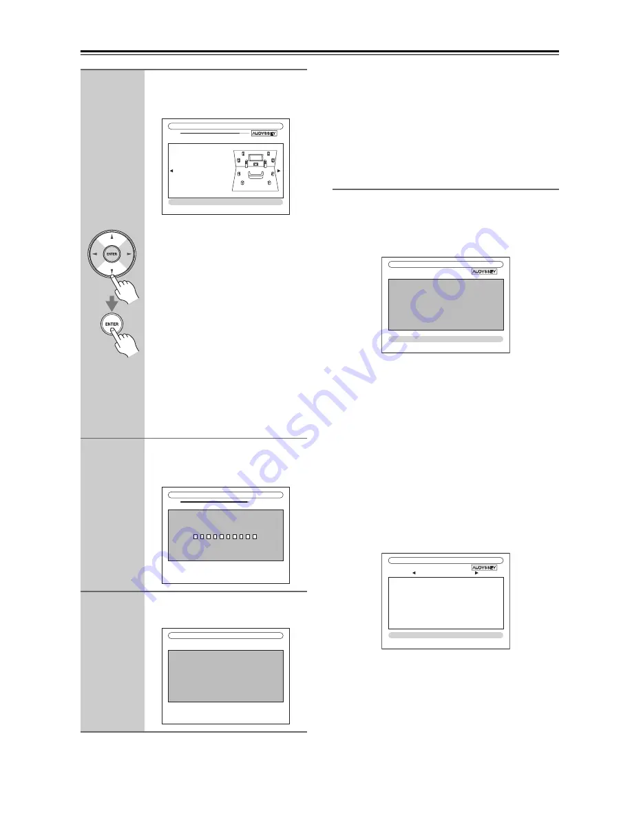
9

When the calculations are com-
plete, the following screen 
appears.

Use the Up and Down [

q

]/[

w

] but-

tons to select an option, and then 
press [ENTER].

The options are:

Save: 

Save the calculated settings and exit 
the room correction and speaker 
setup.

Cancel: 

Cancel the room correction and 
speaker setup.

Note:

You can view the calculated settings for 
the speaker configuration, speaker dis-
tances, and speaker levels by using the 
Left and Right [

e

]/[

r

] buttons.

10

If you selected “Save”, the results are 
saved, and the following screen 
appears.

11

Disconnect the speaker setup 
microphone.

Subwoofer No
Front Full 

Band

Center 40Hz
Surround 120Hz
Front Wide 

Full Band

Front High 

Full Band

Surr Back 

150Hz

Surr Back Ch  

 2ch

-- Review SP Configuration --

MultEQ XT: Auto Setup

Save
Cancel

MultEQ XT: Auto Setup

Saving...

MultEQ XT: Auto Setup

Please, unplug setup microphone.

MultEQ XT: Auto Setup

Retry
Cancel

Ambient noise is too high.

FL : No
SL :  ---
FWL : 

---

FHL :  ---
SBL :  ---
C : ---

FR :  ---
SR :  ---
FWR : 

---

FHR :  ---
SBR : 

---

SW1 : 

---

SW2 : 

---

MultEQ XT: Auto Setup

Retry
Cancel

Speaker Detect Error

Summary of Contents for TX-NR3007

Page 1: ...lowing the instructions in this manual will enable you to obtain optimum performance and listening enjoyment from your new AV Receiver Please retain this manual for future reference Contents Introduct...

Page 2: ...ratus does not operate normally by following the operating instructions Adjust only those controls that are covered by the oper ating instructions as an improper adjustment of other controls may resul...

Page 3: ...astic items on this unit for a long time because they may leave marks on the case This unit s top and rear panels may get warm after prolonged use This is normal If you do not use this unit for a long...

Page 4: ...CS GmbH LIEGNITZERSTRASSE 6 82194 GROEBENZELL GERMANY GROEBENZELL GERMANY ONKYO EUROPE ELECTRONICS GmbH K MIYAGI declare in own responsibility that the ONKYO product described in this instruction manu...

Page 5: ...Using Easy Macros 71 Listening to the Radio 73 Using the Tuner 73 Presetting AM FM Stations 74 Using RDS European models 75 Universal Port Option UP A1 Dock for iPod 77 About the UP A1 Dock 77 Compat...

Page 6: ...module European models 2 Independent Subwoofer Pre Outs SIRIUS 8 Satellite Radio Connectivity North Ameri can models Banana Plug Compatible Speaker Posts 7 Powered Zone 2 3 Internet Radio Connectivit...

Page 7: ...some jurisdictions All rights reserved Xantech is a registered trademark of Xantech Corporation Niles is a registered trademark of Niles Audio Corporation Apple and iPod are trademarks of Apple Inc re...

Page 8: ...e buttons are used to select from the following input sources DVD BD VCR DVR CBL SAT GAME AUX 1 AUX 2 TV TAPE TUNER CD PHONO PORT NET USB f Remote control sensor transmitter 14 The sensor receives con...

Page 9: ...ith video games THX Selects the THX listening modes p DIMMER button 69 North American models This button is used to adjust the display brightness RT PTY TP button 75 European and Asian models This but...

Page 10: ...in parentheses a Speaker channel indicators Indicate the speaker channels used by the current listening mode The following abbreviations indicate which audio channels are outputted for the current li...

Page 11: ...volume level o MUTING indicator 69 Flashes while the AV receiver is muted p Audio input indicators Indicate the type of audio input that s selected as the audio source HDMI ANALOG or DIGITAL a UNIVERS...

Page 12: ...A component video inputs are for con necting components with a component video out put such as a DVD player DVD recorder or DVR digital video recorder They re assignable which means you can assign eac...

Page 13: ...L R SURR BACK ZONE 3 L R FRONT HIGH L R and FRONT WIDE ZONE 2 L R These terminal posts are for connecting the front L R center surround L R surround back zone 3 L R front high L R and front wide zone...

Page 14: ...dvert ently thereby draining the batteries The remote controller may not work reliably if the AV receiver is installed in a rack behind colored glass doors Keep this in mind when installing The remote...

Page 15: ...nformation about the current input source k MUTING button 69 Mutes or unmutes the AV receiver l VOL q w button 67 Adjusts the volume of the AV receiver regardless of the currently selected remote cont...

Page 16: ...tions 2 D TUN button 73 TUNER remote mode only Selects the Direct tuning mode 3 DISPLAY button Displays information about the band frequency preset number and so on 4 CH button 74 Used to select radio...

Page 17: ...dth of the wall as shown Tip To find the best position for your subwoofer while playing a movie or some music with good bass experiment by placing your subwoofer at various positions within the room a...

Page 18: ...V receiver to suit your exact requirements and application Two typical applications are shown below 7 2 channel Playback with Speakers A and Stereo Playback with Speakers B In this example Speakers A...

Page 19: ...corresponding speaker terminal North American models If you are using banana plugs tighten the speaker ter minal before inserting the banana plug Do not insert the speaker code directly into the cent...

Page 20: ...Read the instructions supplied with your speakers Pay close attention to speaker wiring polarity In other words connect positive terminals only to positive terminals and negative terminals only to neg...

Page 21: ...minal 1 Strip 1 2 to 5 8 12 to 15 mm of insulation from the ends of the speaker cables and twist the bare wires tightly as shown 2 Unscrew the terminal 1 2 to 5 8 12 to 15 mm 3 Fully insert the bare w...

Page 22: ...aker to FRONT R When Speakers B is selected as the main front speakers connect the front left speaker to FRONT WIDE ZONE 2 L front right speaker to FRONT WIDE ZONE 2 R The speakers are configured by u...

Page 23: ...nd woofer low terminals Bi amping can only be used with speakers that support bi amping Refer to your speaker manual Bi amping Speaker Hookup Bi amping the Front Speakers A 1 Connect the AV receiver s...

Page 24: ...ble bridging see page 57 When front Speakers A are bridged front Speakers B must be wired normally or not used Notes Use only front speakers with an impedance of 8 ohms or higher for bridging Failure...

Page 25: ...rminals Bi amping can only be used with speakers that support bi amping Refer to your speaker manual Bi amping Speaker Hookup Bi amping the Front Speakers B 1 Connect the AV receiver s FRONT WIDE ZONE...

Page 26: ...to BTL to enable bridging see page 57 When front Speakers B are bridged front Speakers A must be wired normally Notes Use only front speakers with an impedance of 8 ohms or higher for bridging Failure...

Page 27: ...nce your AV receiver is ready for use you ll need to tune into an FM radio station and adjust the position of the FM antenna to achieve the best possible reception 2 Use thumbtacks or something simila...

Page 28: ...a must be grounded in accordance with local regulations to prevent electrical shock haz ards Using a TV FM Antenna Splitter It s best not to use the same antenna for both FM and TV reception as this c...

Page 29: ...ng Video Audio Cable Jack Description HDMI HDMI connections can carry uncompressed stan dard or high definition digital video and audio and offer the best picture and sound quality Video Component vid...

Page 30: ...pera tion with components other than compatible components cannot be guaranteed Set HDMI Control RIHD to On page 114 See Controlling a TV page 143 and Controlling a DVD Player or DVD Recorder page 144...

Page 31: ...addition video signals from a PC are not guaranteed When listening to an HDMI component through the AV receiver set the HDMI component so that its video can be seen on the TV screen on the TV select t...

Page 32: ...receiver at the same time Select Skip in the VideoProcessor setting by pressing the RETURN button repeatedly on the display To reset back to the original setting press the same button at the same tim...

Page 33: ...Analog see page 52 video input signals flow through the AV receiver as shown with composite video and S Video sources being upconverted for the component video output Use this setting if you connect...

Page 34: ...signals for analog line outputs and vice versa For example audio signals connected to an optical or coaxial digital input are not output by the analog TV TAPE OUT If signals are present at more than o...

Page 35: ...EO MONITOR OUT Component video input MONITOR OUT S S Video input MONITOR OUT V Composite video input TV TAPE IN L R Analog audio L R output DIGITAL COAXIAL IN 2 VCR DVR Digital coaxial output DIGITAL...

Page 36: ...EO IN 1 DVD BD Component video output DVD BD IN S S Video output DVD BD IN V Composite video output DVD BD IN L R Analog audio L R output DIGITAL COAXIAL IN 1 DVD BD Digital coaxial output DIGITAL OPT...

Page 37: ...TER SURR L R SURR BACK L R and SUBWOOFER jacks to the 7 1 channel analog audio output on your DVD player If your DVD player has a 5 1 channel analog audio output don t connect anything to the AV recei...

Page 38: ...CR DVR IN L R Analog audio L R output DIGITAL COAXIAL IN 2 VCR DVR Digital coaxial output DIGITAL OPTICAL IN 1 GAME Digital optical output Hint Step 1 Video Connection Choose a video connection that m...

Page 39: ...ut Similarly video signals connected to S Video inputs can only be recorded via S Video outputs If your TV VCR is connected to an S Video input the recording VCR must be connected to an S Video output...

Page 40: ...t video output CBL SAT IN S S Video output CBL SAT IN V Composite video output CBL SAT IN L R Analog audio L R output DIGITAL COAXIAL IN 3 CBL SAT Digital coaxial output DIGITAL OPTICAL IN 1 GAME Digi...

Page 41: ...ME IN S S Video output GAME IN V Composite video output GAME IN L R Analog audio L R output DIGITAL OPTICAL IN 1 GAME Digital optical output Step 1 Video Connection Choose a video connection that matc...

Page 42: ...AUX1 INPUT L AUDIO R Analog audio L R output AUX1 INPUT DIGITAL Digital optical output Step 1 Video Connection Make the connection A Step 2 Audio Connection Choose an audio connection that matches yo...

Page 43: ...ercially available MC head amp or MC transformer Connect your turntable to the head amp or trans former and connect that to the AV receiver s PHONO IN L R jacks You can also use a phono equalizer to c...

Page 44: ...MD or DAT recorder TV TAPE IN L R TV TAPE OUT L R Analog audio L R output Analog audio L R input DIGITAL COAXIAL IN 3 CBL SAT Digital coaxial output DIGITAL OPTICAL IN 1 GAME TX NR3007 DIGITAL OPTICAL...

Page 45: ...connect it to PRE OUT SW1 Connecting a Power Amplifier 2 3 4 5 6 7 8 9 1 Power amplifier Powered subwoofer See Connecting Powered Sub woofers on page 19 for more information 1 Front left speaker 2 Cen...

Page 46: ...A1 Dock that seated iPod is connected the power consumption on standby mode slightly increases Connecting an RI Dock Not all iPod models output video For information about which iPod models are suppo...

Page 47: ...with your other Onkyo components While Zone 2 or Zone 3 is on the Auto Power On Standby and Direct Change u functions do not work Notes Before connecting the power cord connect all of your speakers a...

Page 48: ...ode To prevent any loud surprises when you turn on the AV receiver always turn down the volume before you turn it off or Remote controller AV receiver Smooth Operation in a Few Easy Steps To ensure sm...

Page 49: ...ut Change Monitor Out setting manually Tips The Monitor Out setting can also be set using the VIDEO button on the remote controller This setting can also be performed by using Onscreen Setup Menu see...

Page 50: ...the SETUP button The main menu appears onscreen If the main menu doesn t appear make sure the appropriate external input is selected on your TV 2 Use the Up and Down q w but tons to select 6 Miscella...

Page 51: ...reen 2 Use the Up and Down q w but tons to select item and then press ENTER The submenu appears Press the SETUP button to close the menu Press the RETURN button to return to the previous menu SETUP RE...

Page 52: ...or Out and use the Left and Right e r buttons to select Analog Select this if your TV is connected to the COMPONENT VIDEO MONITOR OUT S MONITOR OUT or V MONITOR OUT HDMI Main Select this if your TV is...

Page 53: ...nd video conversion as necessary 1080i Select this for 1080i output and video conversion as necessary 1080p Select this for 1080p output and video conversion as necessary 1080p 24 Select this for 1080...

Page 54: ...e appropriate CEC Consumer Electronics Control operation is not guaranteed This procedure can also be performed on the AV receiver by using its SETUP button arrow buttons and ENTER button Video Input...

Page 55: ...ng its SETUP button arrow buttons and ENTER button Input selector Default assignment DVD BD IN1 VCR DVR CBL SAT IN2 GAME IN3 AUX 1 AUX 2 TV TAPE TUNER Fixed CD PHONO PORT 1 Press the RECEIVER button f...

Page 56: ...ons to select 1 Input Output Assign and then press ENTER The Input Output Assign menu appears 3 Use the Up and Down q w but tons to select 4 Digital Audio Input and then press ENTER The Digital Audio...

Page 57: ...t Setup 1 Press the RECEIVER button followed by the SETUP button The main menu appears onscreen If the main menu doesn t appear make sure the appropriate external input is selected on your TV 2 Use th...

Page 58: ...r bridged operation The BTL indicator will appear on the display 2 Speaker Setup 1 Speaker Settings 2 Speaker Configuration 3 Speaker Distance 4 Level Calibration 5 Equalizer Settings 6 THX Audio Setu...

Page 59: ...tons to select 2 OSD Setup and then press ENTER The OSD Setup menu appears 4 Use the Up and Down q w but tons to select TV Format and then use the Left and Right e r buttons to select Auto Select thi...

Page 60: ...buttons to select North American models 200kHz 10kHz Select if 200 kHz 10 kHz steps are used in your area 50kHz 9kHz Select if 50 kHz 9 kHz steps are used in your area European and Asian models 10kHz...

Page 61: ...e that best matches yours and position the microphone accordingly when prompted Audyssey MultEQ XT Room Correction and Speaker Setup About Audyssey Dynamic EQ Audyssey Dynamic EQ solves the problem of...

Page 62: ...nected 2 Set the speaker setup micro phone at the Main Listening Posi tion a page 61 and connect it to the SETUP MIC jack The speaker setting menu appears If you change these settings refer to step 5...

Page 63: ...Audyssey MultEQ XT performs more measurements This takes a few minutes MultEQ XT Auto Setup Do not unplug setup microphone Please keep quiet Now measuring MultEQ XT Auto Setup Next Please place setup...

Page 64: ...p See Speaker Configuration page 19 for appropriate settings The front speaker has not been detected 9 When the calculations are com plete the following screen appears Use the Up and Down q w but tons...

Page 65: ...etry Cancel Speaker Detect Error FL Yes SL FWL Yes FHL Yes SBL C Yes FR SR FWR FHR No SBR SW1 SW2 MultEQ XT Auto Setup Retry Cancel Speaker Detect Error FL Yes SL No FWL Yes FHL Yes SBL Yes C Yes FR Y...

Page 66: ...peakers are set to 80 Hz THX crossover see page 95 Sometimes due to the electrical complexities of subwoofers and the interaction with the room THX recommends setting the level and the distance of the...

Page 67: ...V receiver s HDMI outputs COMPONENT VIDEO MONITOR OUT or MONITOR OUT On some DVD players you may need to turn on the digital audio output 3 To adjust the volume use the MASTER VOLUME control or the re...

Page 68: ...s analog no format information is displayed If the input signal is PCM the sampling frequency is displayed If the input signal is digital but not PCM the signal format and the number of channels is di...

Page 69: ...ss the DIMMER button repeatedly to select Normal VOLUME light on Normal VOLUME light off Dim VOLUME light off Dimmer VOLUME light off Alternatively you can use the AV receiver s DIMMER button North Am...

Page 70: ...quire front high or front wide speakers such as Dolby Pro Logic IIz Height or Audyssey Dynamic Surround Expansion are unavailable While you are using Speakers B you cannot use Audyssey MultEQ XT Room...

Page 71: ...utton MY MOVIE default 1 The TV connected to the AV receiver is turned on 2 The Onkyo DVD player con nected to the AV receiver is turned on 3 The AV receiver is turned on 4 The input selector of the A...

Page 72: ...at you pressed flashes twice indicating that the setting has been established Examples When you press the MY MUSIC but ton and want to start the Onkyo Cas sette recorder while holding down TV TAPE but...

Page 73: ...opriate frequency Using the Tuner Use the TUNER input selector button to select either AM or FM In this example FM has been selected Each time you press the TUNER but ton the input source changes betw...

Page 74: ...to select a preset from 1 through 40 4 Press the MEMORY button again to store the station or channel The station or channel is stored and the preset number stops flashing Repeat this procedure for al...

Page 75: ...type see page 76 TP Traffic Program This allows you to search for RDS radio stations that broadcast traffic information see page 76 Notes In some cases the text characters displayed on the AV receiver...

Page 76: ...lect the type of program you want See the table on page 75 RT PTY TP PRESET e r ENTER RT PTY TP 3 To start the search press ENTER The AV receiver searches until it finds a station of the type you spec...

Page 77: ...ock its volume control has no effect If you adjust your iPod models volume control while it s in the UP A1 Dock make sure it s not set too high before you reconnect your headphones The Auto Power On f...

Page 78: ...eat function f DISPLAY button Select Standard or Extended mode 1 g MUTING button 69 Mutes or unmutes the AV receiver h ALBUM button Selects the next or previous album i VOL q w button 67 Adjusts the v...

Page 79: ...tion with the dock PORT Not Support The AV receiver do not support the connected dock PORT UP A1 UP A1 Dock is connected Notes The AV receiver displays the message UP A1 for several seconds after reco...

Page 80: ...rdub audio onto your video recordings This function takes advantage of the fact that when an audio only input source i e TV TAPE TUNER CD or PHONO is selected the video input source remains unchanged...

Page 81: ...ideo games THX button This button selects the THX listening modes Selecting with the Remote Controller LISTENING MODE buttons MOVIE TV button This button selects the listening modes intended for use w...

Page 82: ...ker layout illustration shows which speakers are set to active in the Speaker Configu ration setting see page 95 The LISTENING MODE button illustration shows that listening modes can be selected Liste...

Page 83: ...ovie 3 THX Cinema PLII PLIIx Movie Audyssey DSX 4 2 PLllz Height THX Cinema Neo 6 Cinema THX Cinema Neo 6 Cinema Audyssey DSX 4 2 Neural THX Cinema PLII PLIIx Music 3 THX Music PLII PLIIx Music Audyss...

Page 84: ...SP LAYOUT button depending on the Speaker Configuration setting see page 95 5 This listening mode is not available while you are using Zone 2 Not Available will appear on the display If you turn Zone...

Page 85: ...o DTS HD Master Audio DSD 3 PLIIx Movie PLIIx Music PLIIz Height DolbyEX DolbyEX Audyssey DSX 2 Neo 6 Neo 6 Audyssey DSX 2 Neural Surround Audyssey DSX 4 THX Cinema PLIIx Movie THX Cinema PLIIx Movie...

Page 86: ...eural THX Games THX Surround EX THX Ultra2 Cinema PLIIz THX Ultra2 Cinema THX Ultra2 Music PLIIz THX Ultra2 Music THX Ultra2 Games PLIIz THX Ultra2 Games Orchestra 1 2 Unplugged 1 2 Studio Mix 1 2 TV...

Page 87: ...Center speaker is connected to the AV receiver b Either of Front High speakers or Front Wide speakers is connected to the AV receiver Output can be switched between Front high or Front wide speakers...

Page 88: ...AudysseyDSX 4 2 THX Cinema PLIIz Height THX Cinema THX Music PLIIz Height THX Music THX Games PLIIz Height THX Games Orchestra 1 2 Unplugged 1 2 Studio Mix 1 2 TV Logic 1 2 Game RPG 1 2 Game Action 1...

Page 89: ...ies It can also be used with DVDs or other sources containing multiplexed audio such as karaoke DVDs Multichannel This mode is for use with PCM multichannel sources Dolby Pro Logic IIx Dolby Pro Logic...

Page 90: ...7 1 channel playback Use it with DVDs that bear the DTS ES logo especially those with a DTS ES Matrix soundtrack DTS Neo 6 This mode expands any 2 channel source for up to 7 1 channel playback It uses...

Page 91: ...Surround employs psychoacoustic frequency domain processing which allows delivery of a more detailed sound stage with superior channel separation and localization of audio elements The Neural Surroun...

Page 92: ...figuration 3 Speaker Distance 4 Level Calibration 5 Equalizer Settings 6 THX Audio Setup 1 Multiplex Mono 2 Dolby 3 DTS 4 Audyssey 5 Theater Dimensional 6 LFE Level 7 Direct 1 DVD BD 2 VCR DVR 3 CBL S...

Page 93: ...ntrast 50 to 50 default 0 With this setting you can adjust contrast 50 is the least 50 is the greatest Hue 20 to 20 default 0 With this setting you can adjust the red green balance 20 is the strongest...

Page 94: ...fer Input Sensitivity 0 dB default 5 dB 10 dB 15 dB Some DVD players output the LFE channel from their analog subwoofer output at 15 dB higher than normal With this setting you can change the AV recei...

Page 95: ...n page 57 Speaker Configuration With these settings you can specify which speakers are connected and a crossover frequency for each speaker You can set the crossover frequencies distances and levels o...

Page 96: ...set to None this setting cannot be selected 4 If the Surround setting is set to anything other than Full Band Full Band cannot be selected here 5 If the Powered Zone2 setting is set to Act page 134 t...

Page 97: ...Level Calibration can be set automatically by Audyssey MultEQ XT Room Correction and Speaker Setup see page 61 If you prefer you can adjust the level of each speaker with the built in test tone so tha...

Page 98: ...e Left and Right e r buttons to select a speaker 2 Use the Up and Down q w buttons to select a frequency and then use the Left and Right e r buttons to adjust the level at that frequency The volume at...

Page 99: ...ed subwoofer Note If the Subwoofer setting is set to No this setting cannot be selected page 95 BGC Off Select this to turn off BGC On Select this to turn on BGC Note This setting is only available if...

Page 100: ...the left channel is output Right Only the right channel is output This setting specifies the channel to be used for playing any 2 channel digital source such as Dolby Digital or 2 channel analog PCM s...

Page 101: ...lby Volume Off Dolby Volume off default Low Low Compression Mode becomes active Mid Medium Compression Mode becomes active High High Compression Mode becomes active This setting affects volume the mos...

Page 102: ...Offset provides three offsets from the film level reference 5 dB 10 dB and 15 dB that can be selected when the mix level of the content is not within the standard Dynamic EQ Reference Level Offset 0...

Page 103: ...of the LFE channel for DTS and DTS HD High Resolution sources 3 Sets the level of the LFE channel for multichannel PCM sources Multichannel PCM is input via HDMI 4 Sets the level of the LFE channel fo...

Page 104: ...ve finished press the SETUP button The setup menu closes IntelliVolume With IntelliVolume you can set the input level for each input selector individually This is useful if one of your source compone...

Page 105: ...press ENTER Picture Adjust Using Picture Adjust you can adjust the picture quality and reduce any noise appearing on the screen To view the TV picture while setting press ENTER To return to the previ...

Page 106: ...106 Advanced Setup Continued Zoom Mode This setting determines the aspect ratio Normal Full default Zoom Wide Zoom...

Page 107: ...ingly to achieve the best picture quality If the AV receiver detects the type of content incorrectly due to characteristics of the disc you can select Video or Film manually Edge Enhancement 2 Off Edg...

Page 108: ...st the picture brightness 50 is the darkest 50 is the brightest Contrast 2 50 to 50 default 0 With this setting you can adjust contrast 50 is the least 50 is the greatest Hue 2 20 to 20 default 0 With...

Page 109: ...buttons to select the signal format that you want to set and then use the Left and Right e r buttons to select a listening mode 5 When you ve finished press the SETUP button The setup menu closes List...

Page 110: ...isplay range is Min 0 5 through 99 5 Max Relative Display range is Q dB 81 5 dB through 18 0 dB With this setting you can choose how the volume level is displayed The absolute value 82 is equivalent t...

Page 111: ...an and Asian models See TV Format Setup European and Asian models on page 59 Language See Selecting the Language used for the onscreen setup menus on page 50 Hardware Setup 1 Press the RECEIVER button...

Page 112: ...able to control it with the remote controller Multi Zone See Setting the Multi Zone on page 135 Tuner FM AM Frequency Step North American models AM Frequency Step European and Asian models See FM AM F...

Page 113: ...settings or turn down the AV receiver s volume When the Audio TV Out setting is set to On the remote controller s AUDIO button is disabled If the Monitor Out setting is set to Both Main or Both Sub pa...

Page 114: ...select On This setting is set to On automatically when the above HDMI Control RIHD is set to On for the first time Notes The Power Control setting can be set only when the above HDMI Control RIHD set...

Page 115: ...rmware is displayed The version is made up of the versions of the AV receiver and Onkyo dock if connected Receiver via NET You can update the firmware via Internet Check the network connection before...

Page 116: ...een If the main menu doesn t appear make sure the appropriate external input is selected on your TV 2 Use the Up and Down q w buttons to select 9 Lock Setup and then press ENTER The Lock Setup menu ap...

Page 117: ...select the Direct Pure Audio or THX listening mode This procedure can also be performed on the AV receiver by using its TONE Down e and Up r buttons see page 68 Late Night Function With the Late Nigh...

Page 118: ...n THX listening modes set Loudness Plus setting to Off and set Preserve THX Settings setting to No Dolby Volume Dolby Volume Off Dolby Volume off default Low Low Compression Mode becomes active Mid Me...

Page 119: ...on will not work when the Pure Audio or Direct listening mode is selected to play analog audio Audio Selector You can set priorities of audio output when there are both digital and analog inputs Audio...

Page 120: ...eiver to your home network Internet Access for Internet radio To receive Internet radio your Ethernet network must have Internet access A narrowband Internet connection e g 56K modem ISDN will not pro...

Page 121: ...ernet Radio screen and then press ENTER to start playback Note If you re using a narrowband Internet connection e g 56K modem or ISDN depending on the station Internet radio may not work satisfactoril...

Page 122: ...Server4 Server5 Server6 Server7 Server8 Server9 Server10 1 8 Search Recently Added Artists Album Songs Genre Year Rating Server1 4 Use the Up and Down q w buttons to select an item and then press ENTE...

Page 123: ...repeatedly In Repeat Folder mode all of the songs in the current folder are played repeatedly In Repeat All mode all of the songs on the current server are played repeatedly To cancel repeat playback...

Page 124: ...files contain uncompressed PCM digital audio Sampling rates of 8 kHz 11 025 kHz 12 kHz 16 kHz 22 05 kHz 24 kHz 32 kHz 44 1 kHz 48 kHz 64 kHz 88 2 kHz and 96 kHz are supported Incompatible files canno...

Page 125: ...ion Members of DLNA develop a concept of wired and wireless interoperable networks where digital content such as photos music and videos can be shared through consumer electronics personal computers a...

Page 126: ...button Network Settings 1 Press the RECEIVER button followed by the SETUP button The main menu appears onscreen If the main menu doesn t appear make sure the appropriate external input is selected on...

Page 127: ...your ISP Proxy URL To use a Web proxy enter its URL here Proxy Port If you re using a Web proxy enter a proxy port number here Control This setting enables or disables control over the network Enable...

Page 128: ...ppears To open a folder use the Up and Down q w buttons to select it and then press ENTER 4 or Use the Up and Down q w buttons to select a music file and press the ENTER or Play 1 button to start play...

Page 129: ...the AV receiver s USB port we recommend that you use its AC adapter to power it Do not connect the AV receiver s USB port to a USB port on your computer Music on your computer can not be played throug...

Page 130: ...131 and 133 Zone 2 In your Zone 2 room you can enjoy 2 channel stereo playback and video playback see page 131 The listening modes cannot be used with Zone 2 Zone 3 In your Zone 3 room you can enjoy 2...

Page 131: ...tes With this setup the Zone 2 volume is controlled by the AV receiver Powered Zone2 cannot be used if Speakers Type FrontB is set to Normal Bi Amp or BTL see page 57 Connecting Your Zone 2 Speakers t...

Page 132: ...composite video input on your Zone 2 TV Note The ZONE 2 OUT V jack outputs video from compo nents connected to composite video only Zone 2 12V Trigger When Zone 2 is turned on the output from the 12V...

Page 133: ...setup allows 9 2 channel playback in your main lis tening room and 2 channel stereo playback in Zone 3 with a different source in each room Hookup Use an RCA audio cable to connect the AV receiver s...

Page 134: ...in menu appears onscreen If the main menu doesn t appear make sure the appropriate external input is selected on your TV 2 Use the Up and Down q w buttons to select 2 Speaker Setup and then press ENTE...

Page 135: ...evel as when the AV receiver was last turned off select Last The Zone2 3 Power On Volume cannot be set higher than the Zone2 3 Maximum Volume setting Setting the Multi Zone 1 Press the RECEIVER button...

Page 136: ...2 or ZONE 3 button repeat edly You can also select SIRIUS North American models To select the same source as that of the main room press the ZONE 2 or ZONE 3 button twice Zone 2 Selec tor Source or Zo...

Page 137: ...ting the volume The volume tone and balance functions cannot be set when the Zone2 Out or Zone3 Out setting is set to Fixed page 135 and Powered Zone2 or Pow ered Zone3 setting is set to Not Act page...

Page 138: ...ds them to the AV receiver located in the cabinet via the connecting block Using a Multiroom Kit with Other Components In this setup an IR emitter is connected to the AV receiver s IR OUT jack and pla...

Page 139: ...control code from onscreen setup menu Note This setting can be carried out by using Onscreen Setup Menu only Preprogrammed Remote Control Codes Onkyo DVD player page 144 Onkyo CD player page 147 Onky...

Page 140: ...Brand TV XXXXX OK Now we are ready to transfer data to Remote Please hold remote so that it is facing the receiver Use ENTER button of your remote to activate OK Ready To use the remote controller po...

Page 141: ...tton lights up Notes Remote control codes cannot be entered for the RECEIVER and ZONE buttons Only TV remote control codes can be entered for the TV button Except for the RECEIVER TV and ZONE buttons...

Page 142: ...ents Connected via u 1 Make sure the Onkyo component is con nected with an u cable and an analog audio cable RCA See page 47 for details 2 Enter the appropriate remote control code for the REMOTE MODE...

Page 143: ...navigate menus and select items f SETUP button Displays a menu g 1 3 2 5 4 7 6 buttons Play Pause Stop Fast reverse Fast forward Previ ous and Next These buttons works for combination devices h SEARCH...

Page 144: ...ton Set the TV to On or Standby c TV INPUT button Selects the TV s external inputs d TV VOL q w button Adjust the TV s volume e TOP MENU button Displays a DVD s top menu or a DVD s title f Arrow q w e...

Page 145: ...me e GUIDE button Displays the program guide or navigation list f Arrow q w e r and ENTER buttons Used to navigate menus and select items g SETUP button Displays the video recorders setup menu h Previ...

Page 146: ...n as colored buttons or A B C D buttons f Number buttons Enter numbers The 10 button works as a 10 button or button g DISPLAY button Displays information h MUTING button 69 Mutes or unmutes the AV rec...

Page 147: ...d with the repeat playback function f SEARCH button Used to locate specific points g Number buttons Used to enter track numbers and times for locating specific points The 10 button works as a 10 butto...

Page 148: ...its the On and Standby commands alternately so if your iPod is already on it will remain on when the remote control ler transmits an On command Similarly if your iPod is already off it will remain off...

Page 149: ...NDBY buttons Turns the cassette recorder on or off b Previous and Next 7 6 buttons The Previous 7 button selects the previous track During playback it selects the beginning of the current track The Ne...

Page 150: ...s Setup 5 Use the Up and Down q w but tons to select an item and use the Left and Right e r but tons to change the settings The items are explained below Source DVD BD VCR DVR CBL SAT GAME AUX 1 AUX 2...

Page 151: ...fer will appear To use the remote controller point it at the AV receiver s remote control sen sor as shown below 8 2 Activities Setup My Movie OK Now we are ready to transfer data to Remote Please hol...

Page 152: ...ds will be lost and will have to be learned all over again so don t discard your other remote controllers Deleting Learning Commands 1 While holding down the REMOTE MODE button for the mode in which y...

Page 153: ...ights up about 3 seconds 2 Press the buttons whose actions you want to program into the macro in the order you want them performed For the CD example above you d press the following buttons ON CD Play...

Page 154: ...HONES jack no sound is output by the speakers page 70 If there s no sound from a DVD player connected to an HDMI IN check the DVD player s output settings and be sure to select a supported audio forma...

Page 155: ...57 and 133 There s no sound with a certain signal format Check the digital audio output setting on the con nected device On some game consoles such as those that support DVD the default setting is of...

Page 156: ...selected If you selected Both Main or Both Sub in the Monitor Out setting no picture may appear on your TV that is connected to a secondary HDMI output not a priority HDMI output In this case change t...

Page 157: ...e remote control code first page 142 To control an Onkyo component that s not connected via u or another manufacturer s component point the remote controller at the component Be sure to enter the appr...

Page 158: ...a server or Internet radio station recheck the AV receiver s IP address on Network screen Check the Network settings page 126 Can t access the music files on a USB device Make sure the USB device is...

Page 159: ...Input Select the relevant input selector and assign it to page 54 3 On the main menu select 1 Input Output Assign and then select 3 Component Video Input page 55 If the video source is connected to CO...

Page 160: ...Speaker Impedance 4 16 Input Sensitivity Output Level and Impedance 1 Vp p 75 Component andS VideoY 0 7 Vp p 75 Component PB CB PR CR 0 28 Vp p 75 S Video C 1 Vp p 75 Composite Component Video Frequen...

Page 161: ...aker Impedance 4 16 Input Sensitivity Output Level and Impedance 1Vp p 75 Componentand S Video Y 0 7 Vp p 75 Component PB CB PR CR 0 28 Vp p 75 S Video C 1 Vp p 75 Composite Component Video Frequency...

Page 162: ...t of Macrovision Output NTSC HDMI COMPONENT S VIDEO COMPOSITE 1080p 1080i 720p 480p 480i 1080p 1080i 720p 480p 480i 480i 480i HDMI 1080p 1080i 720p 480p 480i COMPONENT 1080p 1080i 720p 480p 1 1 480i 1...

Page 163: ...163 Memo...

Page 164: ...Fax 1 201 785 2650 http www us onkyo com ONKYO EUROPE ELECTRONICS GmbH Liegnitzerstrasse 6 82194 Groebenzell GERMANY Tel 49 8142 4401 0 Fax 49 8142 4401 555 http www eu onkyo com ONKYO EUROPE ELECTRON...

Reviews: