background image

16

Speaker setup

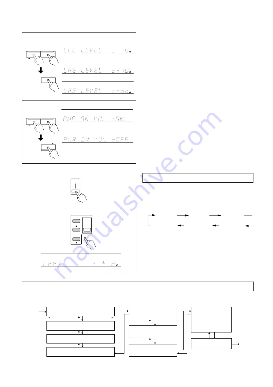
9. Press the PARAMETER SELECTOR

®

 button to display

the LFE LEVEL parameter, and press the PARAMETER
CONTROLLER 

/

®

 buttons to set the value.

You can set the LFE LEVEL parameter for the Dolby digital or
DTS playback.
In general, leave this parameter to 0dB.
Pressing the PARAMETER CONTROLLER 

/

®

 buttons

repeatedly toggles the values. Display the desired value.
With the Dolby digital sound, the parameter value changes as
shown on the left. With the DTS sound, the parameter value
changes in the following order: +10dB, 0dB, –

dB.

Also, refer to “LFE level attenuation” on page 22.

10. Press the PARAMETER SELECTOR 

®

 button. The

POWER ON VOLUME ON/OFF parameter appears.
Press the PARAMETER CONTROLLER 

/

®

 buttons to

toggle between ON and OFF.
ON: 
Power On Volume function is enabled.
OFF: Power On Volume function is disabled.
Display the desired setting and press the PARAMETER
SELECTOR 

®

 button.

Refer to page 18 for more information on the Power On Volume
function.

Note: 
Even if the parameter has already been set to ON, turn it OFF,
then turn it ON again to enable the Power On Volume function.

Use the remote controller and produce the test tone to adjust the
level of the connected speakers.

1. Press the TEST TONE button.

Each speaker produces the test tone (pink noise) in the follow-
ing order:

2. To adjust the level of each speaker, press the CH SEL button

to select a speaker and press the LEVEL

π

/

 buttons to

raise or lower the level.
The test tone should sound at the same level when you hear it in
your listening position. You can adjust the level in the range
between –12dB and +12dB.

3. Press the TEST TONE button to complete adjustment.

Test Tone (Remote controller only)

LEFT

L-SURROUND

CENTER

RIGHT

R-SURROUND

SUBWOOFER

(Front L ch)

(Center ch)

(Front R ch)

(Subwoofer)

(L-Surround)

(R-Surround)

PARAMETER SELECTOR

PARAMETER CONTROLLER

PARAMETER SELECTOR

PARAMETER CONTROLLER

or

9

or

10

or

LEVEL

CH SEL

TEST

TONE

1, 3

2

TEST

TONE

This chart shows how the display changes when the PARAMETER SELECTOR buttons are pressed. Selecting a parameter and pressing the
PARAMETER CONTROLLER button will change the value or setting for the selected parameter.

Parameter selector

START

Subwoofer   YES / NO

FRONT Speaker   LARGE / SMALL

FRONT Speaker Distance

0.3 ~ 9m, 1 ~ 30ft

Center Speaker Distance

0.3 ~ 9m, 1 ~ 30ft

POWER ON VOLUME

ON / OFF

Surround Speaker Distance

0.3 ~ 9m, 1 ~ 30ft

QUIT

LFE Level Attenuator

Dolby Digital:

0dB / –10dB / –

dB

DTS:

+10dB / 0dB / –

dB

Center Speaker   LARGE / SMALL / NONE

Surround Speaker   LARGE / SMALL / NONE

PARAMETER SELECTOR

PARAMETER SELECTOR

10.

Summary of Contents for TX-DS484

Page 1: ...autions 3 Features 4 Supplied accessories 4 Before operating this unit 5 Preparation Audio equipment connections 6 Video equipment connections 7 Connecting other devices 8 Connecting speakers 10 Posit...

Page 2: ...o provide some protection against voltage surges and built up static charges Article 810 of the National Electrical Code ANSI NFPA 70 provides information with regard to proper grounding of the mast a...

Page 3: ...the terminal which is marked with the letter N or coloured black The wire which is coloured brown must be connected to the termi nal which is marked with the letter L or coloured red IMPORTANT A 5 amp...

Page 4: ...e trademarks of Dolby Laboratories Confidential Unpublished Works 1992 1997 Dolby Laboratories Inc All rights reserved Supplied accessories Check that the following accessories are supplied with this...

Page 5: ...l vary depending on usage Point the remote controller toward the remote control sensor The STANDBY indicator lights up when the unit receives a signal from the remote controller Notes Place the unit a...

Page 6: ...D 2 1 FRONT R R A B L L R L VIDEO 1 CENTER SUB WOOFER R L V VIDEO 2 DVD CENTER R L DIGITAL INPUT FRONT SPEAKERS R L SPEAKER CENTER SPEAKERS SURROUND COAXIAL COAXIAL OPTICAL MULTI CH INPUT OUT IN IN IN...

Page 7: ...the corresponding analog input See page 19 Video equipment connections On each pair of input jacks a red connector marked R corresponds to the right channel and a white connector marked L to the left...

Page 8: ...O OUT VIDEO OUT SURROUND OUT L Left R Right L R V Video V Audio connection cable Video connection cable On each pair of input jacks a red connector marked R corresponds to the right channel and a whit...

Page 9: ...European models Capacity is total 100 watts ON REMOTE CONTROL CD AM FM 75 ANTENNA GND PHONO R L R L PLAY REC OUT IN MONI TOR OUT SUB WOOFER PRE OUT SURROUND 2 1 FRONT R R A B L L R L TAPE VIDEO 1 CENT...

Page 10: ...ROL CD AM FM 75 ANTENNA GND PHONO R L R L PLAY REC OUT IN MONI TOR OUT SUB WOOFER PRE OUT SURROUND 2 1 FRONT R R A B L L R L TAPE VIDEO 1 CENTER SUB WOOFER R L V VIDEO 2 DVD CENTER R L DIGITAL INPUT F...

Page 11: ...er Left Front speaker Right Connecting the power Before you plug in the receiver confirm that all connections have been made properly Turning on this receiver s power may cause a momentary power surge...

Page 12: ...e same antenna for both FM and TV or VCR recep tion since the FM and TV or VCR signals can interfere with each other If you must use a common FM TV or VCR antenna use a directional linkage type splitt...

Page 13: ...siderations below regard ing the location Keep the antenna away from noise sources neon signs busy roads etc It is dangerous to put the antenna close to power lines Keep it well away from power lines...

Page 14: ...the type and distance TEST TONE button Use this button to adjust the level of each speaker CH SEL button Use this button to select a speaker Before operating your stereo system you need to set the ty...

Page 15: ...ROLLER button repeatedly increases the value Pressing the PARAMETER CONTROLLER button repeat edly decreases the value Set the value closest to the actual distance 7 Press the PARAMETER SELECTOR button...

Page 16: ...the connected speakers 1 Press the TEST TONE button Each speaker produces the test tone pink noise in the follow ing order 2 To adjust the level of each speaker press the CH SEL button to select a sp...

Page 17: ...olume of the Front Center Surround speakers and subwoofer simultaneously Turning the control clockwise increases the volume level Turning the control counter clockwise decreases the volume level DIMME...

Page 18: ...r OFF appears 3 Press the PARAMETER CONTROLLER or button to select ON Even if the parameter has already been set to ON turn it OFF then turn it ON again to enable the Power On Volume function The orig...

Page 19: ...eep function Press the SLEEP button until it returns to the selected input source name or The timer setting will be cancelled if you turn off the power to the unit Press the MUTING button on the remot...

Page 20: ...a realistic sound that could be heard in the theaters and con cert halls DOLBY DIGITAL Select this option when you play a DVD video that has a mark DTS Select this option when you play a DVD player la...

Page 21: ...player while play ing a DTS source a short noise may be heard This is not a mal function 4 The DTS indicator on the TX DS484 lights up while it plays the DTS source When playback concludes and the DTS...

Page 22: ...N BASS TREBLE C D PHONES DIMMER TX DS484 AV RECEIVER AM FM DVD PHONO 1 VIDEO 2 VIDEO TI CH INPUT MUL TAPE STANDBY TUNING CLEAR MEMORY FM MODE SPEAKERS A B LATE NIGHT SURROUND MODE PARAMETER CONTROLLER...

Page 23: ...lly FM auto tun ing mode When a broadcast is received scanning stops When an RDS Radio Data System station broadcasting PS Pro gram Service Name information is received the RDS indicator lights up and...

Page 24: ...desired memory number using PRESET button 4 Press the MEMORY button Total of 30 stations can be stored in the memory 1 Select the tuner as the source by pressing the AM or FM input selector button on...

Page 25: ...record If you select DVD VIDEO 1 or VIDEO 2 only the audio will be recorded If you select FM or AM set the tuner to the station you want to record 3 Set the tape deck in recording mode Start playing...

Page 26: ...that is connected to the VIDEO 2 terminal Refer to the video disc player video camcorder DVD or VCR instruction manuals for additional information Recording data from a video disc player or a video ca...

Page 27: ...together Move them farther apart Rough or scratchy sound High range is not clear Stylus of turntable pick up is worn Turntable stylus tip is dirty Treble control too high Replace Clean Turn treble con...

Page 28: ...Hz to 20 kHz 0 8 dB Tone Control Bass 10 dB at 50 Hz Treble 10 dB at 10 kHz Signal to Noise Ratio Phono 80 dB IHF A 5 mV input CD Tape 100 dB IHF A Signal sensitivity and impedance 1 Vp p 75 ohms DVD...

Page 29: ...4 FM MODE button 23 24 MEMORY button 24 7 Display Refer to the Display illustration 8 PARAMETER SELECTOR buttons 14 16 9 PARAMETER CONTROLLER buttons 14 16 10 MASTER VOLUME control knob 17 18 11 TREBL...

Page 30: ...ns TUNER 24 31 PRESET Preset memory up down buttons 11 DVD operation buttons 31 12 Channel selector button CH SEL 14 16 18 13 Test tone button TEST TONE 14 16 14 Volume buttons VOLUME 17 Volume contro...

Page 31: ...Down Up Fast Rewind Fast Forward Listening to the radio Using an Onkyo tape deck Using an Onkyo CD player Using an Onkyo DVD player POWER SLEEP DIMMER SUR MODE VIDEO 1 VIDEO 2 TAPE DVD C D C D DVD TUN...

Page 32: ...A Tel 201 825 7950 Fax 201 825 8150 E mail onkyo onkyousa com ONKYO EUROPE ELECTRONICS GmbH Industriestrasse 20 82110 Germering GERMANY Tel 089 84 93 20 Fax 089 84 93 226 E mail info onkyo de ONKYO C...

Reviews: