background image


45


Recording


This chapter explains how to record the selected input 
source to an AV component with recording capability, 
and how to record audio and video from two different 
sources.

You can record only to AV components that are con-
nected to the TAPE OUT or VIDEO 1 OUT jacks.
See pages 24–33 for information on connecting your AV 
components to the AV receiver. 


Notes:


• You cannot record from AV components that are con-

nected to the digital inputs. You must use analog con-
nections.

• The surround effects produced by the surround and 

DSP listening modes cannot be recorded.

• You cannot record from an AV component that is con-

nected to the multichannel input.

• If you select another input source while recording, that 

input source will be recorded instead.

With this function, you can record audio and video from 
different sources, allowing you to overdub audio onto 
your video recordings. This function takes advantage of 
the fact that when an audio-only input source (i.e., 
TAPE, TUNER, or CD) is selected, the video input 
source remains unchanged. For example, if you first 
select the VIDEO 3 input source, followed by the CD 
input source, you can watch the video from the VIDEO 3 
input and listen to the audio from the CD input.

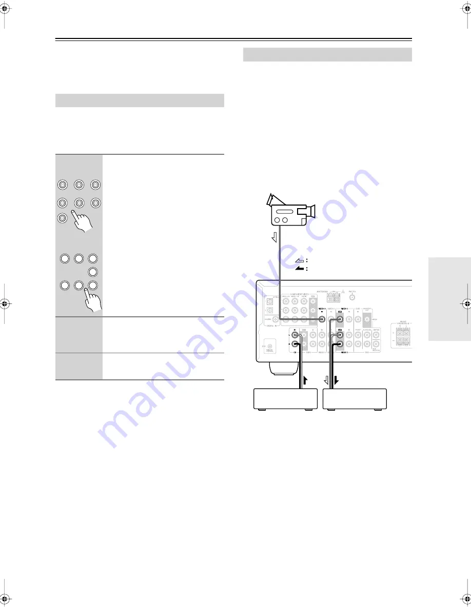
In the following example, audio from the CD player con-
nected to the CD IN jacks, and video from the camcorder 
connected to the VIDEO 3 IN jack are recorded by the 
VCR, which is connected to the VIDEO 1 OUT jacks.


1.


Prepare the camcorder and CD player 
for playback.


2.


Prepare the VCR for recording.


3.


Press the [VIDEO 3] input selector but-
ton.


4.


Press the [CD] input selector button.


This selects the CD player as the audio source, but 
leaves the camcorder as the video source.


5.


Start recording on the VCR and start 
playback on the camcorder and CD 
player.


The video from the camcorder and the audio from 
the CD player are recorded by the VCR.


Recording the Input Source


1


Use the input selector buttons to 
select the AV component that 
you want to record.


Audio signals from the selected input 
source are output by the VIDEO 1 OUT 
and TAPE OUT jacks.
You can listen to the source while 
recording. The AV receiver’s VOL-
UME control has no effect on record-
ing.


2


Start recording on the AV compo-
nent connected to the TAPE OUT 
or VIDEO 1 OUT jacks.


3


Start playback on the source AV 
component.

DVD

VIDEO 1/VCR

VIDEO 2

VIDEO 3

TAPE

TUNER

CD

V

1

V

2

V

3

C D

TAPE

TUNER

DVD

Remote

controller


Recording from Different AV Sources

Camcorder

VCR

CD player

video signal
audio signal

HT-SR600̲En.book Page 45 Wednesday, December 27, 2006 4:11 PM

Summary of Contents for HT-SR600 - 5.1 Home Theater Entertainment System

Page 1: ...efore making connections and plugging in the unit Following the instructions in this manual will enable you to obtain optimum performance and listening enjoyment from your new 5 1ch Home Theater Sys t...

Page 2: ...aratus does not operate normally by following the operating instructions Adjust only those controls that are covered by the operating instructions as an improper adjustment of other controls may resul...

Page 3: ...rear panels may get warm after prolonged use This is normal If you do not use this unit for a long time it may not work properly the next time you turn it on so be sure to use it occasionally For U S...

Page 4: ...m age will affect the sound quality Subwoofer is designed to be used in the upright verti cal position only Do not use it in the horizontal or tilted position If the unit is used near a turntable CD p...

Page 5: ...round Speakers 3 1 4 8 cm cone full range speaker 6 ohm impedance Color coded speaker terminals and speaker cable SKW 350 Bass Reflex Subwoofer 8 20 cm cone woofer Color coded speaker terminals and sp...

Page 6: ...ower plug adapter Only supplied in certain countries Use this adapter if your AC outlet does not match with the plug on the AV receiver s power cord Adapter varies from country to country American typ...

Page 7: ...work reliably if the AV receiver is subjected to bright light such as direct sun light or inverter type fluorescent lights Keep this in mind when installing If another remote controller of the same t...

Page 8: ...rce H DIGITAL INPUT button 35 54 This button is used to assign the digital inputs and to specify the format of digital input signals I DIMMER or RT PTY TP button 41 42 This button is used to adjust th...

Page 9: ...he DVD analog multichannel input R RETURN button 48 50 51 53 This button is used to return to the previously dis played setup menu S SETUP button 48 50 53 This button is used to access various setting...

Page 10: ...nt The AV receiver s remote controller can then be used to control that component To use you must make an analog audio connec tion RCA between the AV receiver and the other component even if they are...

Page 11: ...aker mount bracket inserts These threaded inserts can be used to attach the speaker to a speaker mount or bracket See page 21 for mounting instructions Note Use commercially available machine screws t...

Page 12: ...the AV receiver To set the remote controller to RECEIVER mode press the RECEIVER REMOTE MODE button How to Use the Remote Controller 1 Use the REMOTE MODE buttons to select a mode 2 Use the buttons su...

Page 13: ...avail able listening modes J TEST TONE CH SEL LEVEL LEVEL buttons 34 44 51 These buttons are used to adjust the level of each speaker K DISPLAY button 37 This button is used to display various informa...

Page 14: ...This button is used to display information about the current disc title chapter or track on the DVD player s display including the elapsed time remain ing time total time and so on K CLR button This...

Page 15: ...emaining time total time and so on F CLR button This button is used to cancel functions and to clear entered numbers G RANDOM button This button is used with the random playback func tion H REPEAT but...

Page 16: ...and to clear entered numbers F RANDOM button This button is used with the random playback func tion G REPEAT button This button is used to set the repeat playback func tions H PLAY MODE button This b...

Page 17: ...omponent s menu buttons Select options on the HDD component s menu ENTER button Confirms the selection on the HDD component s menu G RANDOM button This button is used with the random playback func tio...

Page 18: ...o start reverse playback D Rewind FF buttons The Rewind button is used to start rewind The FF button is used to start fast forward TAPE Mode TAPE 7 To select your Cassette deck as the input source pre...

Page 19: ...bout ear level and equally spaced from the TV Angle them inward Surround left and right speakers SKM 350S L R These speakers are used for precise sound position ing and to add realistic ambience Posit...

Page 20: ...so may damage the AV receiver Don t connect more than one cable to each speaker termi nal Doing so may damage the AV receiver Don t connect one speaker to several terminals The AV receiver s positive...

Page 21: ...betweenthewall and the base of the screw head as shown We recommend that you consult a home installa tion professional Threaded inserts for machine screws are provided on the rear of each speaker for...

Page 22: ...tune into an FM radio station and adjust the position of the FM antenna to achieve the best possible reception 2 Fully extend the antenna and point it in various directions to find the best recep tio...

Page 23: ...h local regulations to prevent electrical shock haz ards Using a TV FM Antenna Splitter It s best not to use the same antenna for both FM and TV reception as this can cause interference problems If ci...

Page 24: ...ctions Left white Right red Yellow Analog audio Composite video Left white Right red Yellow Right Wrong Video Cable Jack Description Component video cable Component video separates the luminance Y and...

Page 25: ...f you connect your DVD player to the COMPONENT VIDEO DVD IN a video signal will be output by the COMPONENT OUT but not by any com posite video outputs Video Input Output Diagram Audio Connection Forma...

Page 26: ...ut jacks connect your DVD player to the AV receiver s COMPONENT VIDEO DVD IN jacks And connect the AV receiver s COMPONENT VIDEO OUT jacks to your TV This will provide better picture quality than conn...

Page 27: ...assignment to OPT1 or OPT 2 see page 35 Coaxial connections perform the same as optical ones Optionally connecting your DVD player s audio out L R jacks to the AV receiver s DVD IN FRONT L R jacks wi...

Page 28: ...ideo output jacks to the AV receiver s COMPONENT VIDEO VIDEO 1 IN jacks and connect the AV receiver s COMPONENT VIDEO OUT jacks to your TV s component video in jacks This offers better picture quality...

Page 29: ...L R jacks to your VCR s audio input jacks A a VCR DVD recorder HT R340 Signal Flow Connecting a Camcorder Games Console or Other Device AUDIO OUT L R VIDEO IN VIDEO OUT a A Step 1 Video Connection Co...

Page 30: ...ty than composite video Connect a coaxial feed from a TV antenna to your set top box s antenna input jack e g RF IN and connect your set top box s antenna output jack e g RF OUT to your TV s antenna i...

Page 31: ...r your turntable with built in phono preamp s audio output jacks to the AV receiver s CD IN L R jacks With connection you can listen to and record audio from the CD player or turntable If your CD play...

Page 32: ...OUT L R S VIDEO OUT To TV directly Connect one or the other Signal Flow HT R340 Connecting a Cassette CDR MiniDisc or DAT Recorder COAXIAL OUT OPTICAL OUT OUT PLAY L R a a IN RED L R b c Cassette reco...

Page 33: ...only cables for connections cables are supplied with Onkyo players DVD CD etc Some components have two jacks You can connect either one to the AV receiver The other jack is for connecting additional c...

Page 34: ...r or RECEIVER Smooth Operation in a Few Easy Steps To ensure smooth operation here s a few easy steps to help you configure the AV receiver before you use it for the very first time These settings onl...

Page 35: ...ent DVD COAX VIDEO 1 VCR VIDEO 2 OPT 1 VIDEO 3 TAPE CD OPT 2 1 Press the input selector button for the source that you want to assign Digital inputs cannot be assigned to the TUNER input source 2 Pres...

Page 36: ...ote controller to select the speaker set that you want to use Pressing the remote controller s SPA B button cycles through the following settings Speaker Set A Speaker Set A B Speaker Set B Off The A...

Page 37: ...ds then the previous display reap pears Interpreting Surround Channel Information A The number of front channels front left front right and center B The number of surround channels surround left and s...

Page 38: ...ning to the Radio 1 Use the TUNER input selector button to select either AM or FM In this example FM has been selected Actual display depends on country 1 Press the SETUP button to dis play 0 Hardware...

Page 39: ...ER CD MASTER VOLUME A SPEAKERS B 2 4 3 MEMORY TUNING PRESET ENTER MEMORY TONE STEREO LISTENING MODE DISPLAY DIGITAL INPUT RT PTY TP MEMORY TUNING MODE RETURN TUNING PRESET ENTER SETUP STANDBY STANDBY...

Page 40: ...from an RDS station is weak RDS data may be displayed intermittently or not at all Program Types Used in Europe PTY RDS indicator Type Display Description None NONE No program type News reports NEWS...

Page 41: ...ODE RETURN TUNING PRESET ENTER SETUP STANDBY STANDBY ON CLEAR PHONES MULTl CH DVD VIDEO 1 VCR VIDEO 2 VIDEO 3 TAPE TUNER CD MASTER VOLUME A SPEAKERS B 2 1 3 5 TUNER RT PTY TP TUNING PRESET ENTER 4 To...

Page 42: ...B to 10 dB in 2 dB steps Treble You can boost or cut high frequency sounds output by the front speakers from 10 dB to 10 dB in 2 dB steps Note To bypass the bass and treble tone circuits select the Di...

Page 43: ...ress the remote controller s MUTING button The output is muted and the MUTING indicator flashes on the display as shown MUTING MENU TOP MENU SP A B SETUP RETURN PLAYLIST PLAYLIST RANDOM SUBTITLE PLAY...

Page 44: ...when the AV receiver is set to Standby Multichannel DVD Input While the multichannel DVD input is selected you can adjust the level of each 5 1 channel input individually from 12 dB to 12 dB 30 to 12...

Page 45: ...tch the video from theVIDEO 3 input and listen to the audio from the CD input In the following example audio from the CD player con nected to the CD IN jacks and video from the camcorder connected to...

Page 46: ...nnot be selected while speaker set A is off TONE STEREO LISTENING MODE DISPLAY DIGITAL INPUT RT PTY TP MEMORY TUNING MODE RETURN TUNING PRESET ENTER SETUP STANDBY STANDBY ON CLEAR PHONES MULTl CH DVD...

Page 47: ...ar the DTS logo Neo 6 This mode provides 5 1 channel playback from 2 chan nel sources It offers five full bandwidth channels with excellent separation There are two modes of operation Cinema mode for...

Page 48: ...nel is output R Only the right channel is output Using the Audio Adjust Functions 1 Press the RECEIVER button fol lowed by the SETUP button MUTING MENU TOP MENU SP A B SETUP RETURN PLAYLIST PLAYLIST R...

Page 49: ...surround sound from 2 channel stereo sources With this setting you can specify by how much the front left and right channel output is attenuated in order to create the center channel It can be adjuste...

Page 50: ...PEAT RC 646S TAPE ON STANDBY DIMMER SLEEP INPUT SELECTOR REMOTE MODE V1 V2 V3 CD TAPE TUNER DVD MULTI CH LISTENING MODE DISPLAY OR EQ TESTTONE CH SEL SURROUND STEREO CINE FLTR LEVEL LEVEL L NIGHT VOL...

Page 51: ...he Up and Down buttons to select 3 Level Cal and then press the ENTER but ton A pink noise test tone is output by the front left speaker 3 Turn up the volume so that you can hear the test tone suffi c...

Page 52: ...VD input is being used Cone diameter RECEIVER SETUP ENTER 4 Use the Down button to select Front and then use the Left and Right buttons to select Small or Large Small Select if the front speakers are...

Page 53: ...and the Front setting step 4 is set to Large in the Speaker Con figuration on page 52 7 Use the Down button to select Crossover and then use the Left and Right but tons to select a crossover fre quen...

Page 54: ...in to select PCM DTS or Auto DTS or PCM The DTS or PCM indicator depending on which format you have set flashes and only signals in that format are output Digital signals in other formats are ignored...

Page 55: ...doesn t have a phono preamp built in you must connect one between it and the AV receiver If your turntable uses an MC cartridge you must con nect an MC head amp or an MC transformer and a phono preamp...

Page 56: ...level sampling rate or frequency response changed and the AV receiver doesn t recog nize it as a genuine DTS signal In such cases you may hear noise When playing DTS program material using the pause...

Page 57: ...must make an connection and an analog audio connection RCA between the compo nent and AV receiver even if they are connected digi tally page 33 Recording Others The AV receiver contains a microcompute...

Page 58: ...er Impedance 6 16 Input Sensitivity Output Level and Impedance 1 Vp p 75 Component 0 7 Vp p 75 Component PB CB PR CR 1 Vp p 75 Composite Component Video Frequency Response 5 Hz 50 MHz Tuning Frequency...

Page 59: ...ype color coded Keyhole slot 2 Threaded insert North American model 1 4 screw Depth 5 16 Other models 5 mm screw Depth 8 mm Grille Fixed Other Magnetic shielding Type 2 Way Bass reflex Impedance 6 Max...

Page 60: ...Fax 201 785 2650 http www us onkyo com ONKYO EUROPE ELECTRONICS GmbH Liegnitzerstrasse 6 82194 Groebenzell GERMANY Tel 49 8142 4401 0 Fax 49 8142 4401 555 http www eu onkyo com ONKYO EUROPE UK Office...

Reviews: