DV-SP501
SERVICE PROCEDURES-2
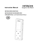
Factory-shipped condition.
Connect the power cord to inlet terminal.
Push button "ON" (Mechanical SW). Lighting the LED condition.
Press the [
STOP
] and [
STANDBY
] same time with NO DISC condition.
Push button "STANDBY".
Pull out the power cord.
INITIALIZING
2. Safety-check out
(Only U.S.A. model)
After correcting the original service problem perform the
following safety check before releasing the set to the customer
Connect the insulating-resistance tester between the plug of
power supply cord and terminal GND on the back panel.
Specifications: More than 10M ohm at 500V
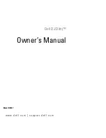
REMOVE THE SOLDER OF LASER DIODE SHORT
When replace the mechanism or DVD main PC board.
Shorting the solder of Shot-circuit land. (2 positions)
Short Land
Mechanism
Summary of Contents for DV-SP501
Page 40: ...DV SP501 IC BLOCK DIAGRAM TERMINAL DESCRIPTION IC301 STM6316ATXXA FRONT END IC Block Diagram...
Page 51: ...DV SP501 IC BLOCK DIAGRAM TERMINAL DESCRIPTION IC101 M63018FP BTL DRIVER 2 Pin Function...
Page 82: ......
Page 83: ......
Page 84: ......
Page 85: ......
Page 86: ......
Page 87: ......
Page 88: ......
Page 89: ......
Page 90: ......
Page 91: ...UR...