ON
STANDBY
DISPLAY
MENU
SETUP
TOP MENU
RETURN
AUDIO
ANGLE SUBTITLE ZOOM
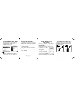
RC-616DV
CLEAR
OPEN/
CLOSE
ENTER
1
2
3
6
7
8
9
0
4
5
PLAY
MODE
DV-SP404
SERVICE MANUAL
SERVICE MANUAL
DVD PLAYER
Black and Silver models
MODEL
DV-SP404
Ref. No. 3947
072006
110-240V AC, 50/60Hz
120V AC, 60Hz
BTUA, STUA
BTDD, STDD
(For USA/Canada, Black/ Silver)
RC-616DV
SAFETY-RELATED COMPONENT
WARNING!!
COMPONENTS IDENTIFIED BY MARK ON THE
SCHEMATIC DIAGRAM AND IN THE PARTS LIST ARE
CRITICAL FOR RISK OF FIRE AND ELECTRIC SHOCK.
REPLACE THESE COMPONENTS WITH ONKYO
PARTS WHOSE PART NUMBERS APPEAR AS SHOWN
IN THIS MANUAL.
MAKE LEAKAGE-CURRENT OR RESISTANCE
MEASUREMENTS TO DETERMINE THAT EXPOSED
PARTS ARE ACCEPTABLY INSULATED FROM THE
SUPPLY CIRCUIT BEFORE RETURNING THE
APPLIANCE TO THE CUSTOMER.