background image


High


Technology


Medical


Devices


6


|


Sreznevského


17,


831


03


Bratislava,


Slovakia


Tel:


+421


2


446


409


77

;


Mobile:


+421


948


610


228,


+421


903


114


944

;


Mail:


[email protected];


Web:


www.onkocet.eu


Functional


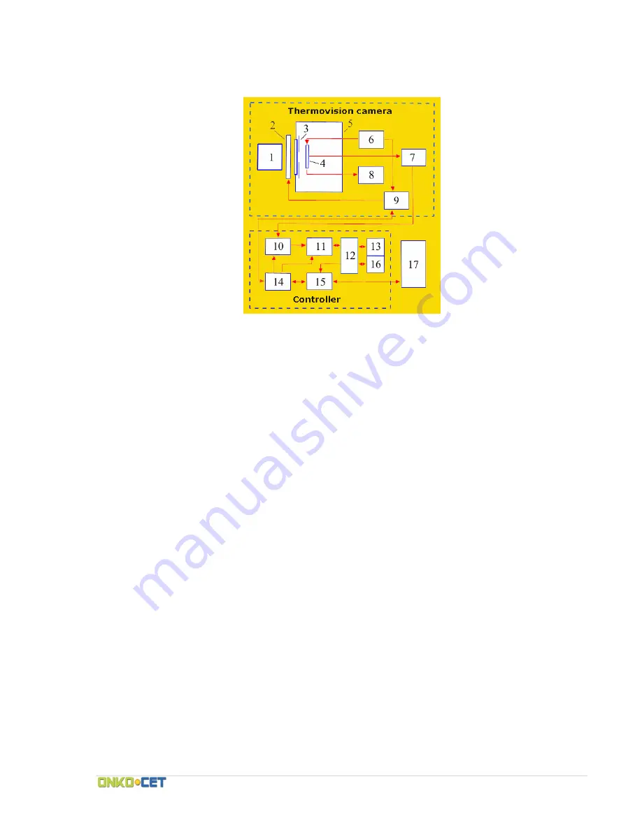
scheme


of


SVIT


Fig.


2.


The


simplified


scheme


of


the


complete


device


set


1

  ‐ 

lens,


2

  ‐ 

the


calibration


device,


3

  ‐ 

cold


diaphragm,


4

  ‐ 

matrix


[FPU],


5

  ‐ 

vacuum


cryostat


with


the


clear


window,


6

  ‐ 

generator


of


the


managers


of


pulse


and


constant


stresses,


7

  ‐ 

amplifier


with


the


differential


output,


8

 ‐ 

temperature


gauge


[FPU]

 ‐ 

the


automatic


weapon


of


the


switching


on


of


the


bias


voltage


of


the


InAs


base


layer,


9,14

 ‐ 

units


for


control


and


synchronization,


10

 ‐ 

ACP,


11

 ‐ 

adder,


12

 ‐ 

dispatcher


of


memory,


13,16

 ‐ 

memory


banks,


15

 ‐ 

unit


of


connection


to


the


computer,


17

 ‐ 

the


computer


The


thermal


radiation


of


the


observed


scene


is


focused


by


lens


(1)


to


the


matrix


of


hybrid


microcircuit


(4),


established


in


the


vacuum


cryostat


(5).


The


level


of


background


gating


is


limited


by


cold


diaphragm


(3).


All


constant


and


surge


voltages


necessary


for


the


work


of


photoreceiver


device


are


assigned


by


generator


(6).


The


device


of


calibration


consists


of


two


mobile


shutters


(specular


and


black),


controlled


by


electromagnets.


Electromagnets


are


governed


by


the


block


(9),


which


also


transfers


into


the


block


(14)


the


pulses,


which


synchronize


the


work


of


ATsP


(10),


adder


(11),


USB


connection


unit


via


USB


port


(15)


and


block


of


the


transmission


of


information


about


the


state


of


automate


(8).


Signal


from


the


matrix


photoreceiver


device


will


be


given


to


the


entrance


of


amplifier


(7).


The


amplified


useful


signal


is


transferred


to


the


personal


computer


after


processing


in


the


controller


(10


16).


On


the


housing


of


infrared


camera


there


are:


the


ring


of


image


focusing,


USB


2.0


port


for


the


connection


to


the


computer,


connector


for


synchronization


(7

pin


connector)


and


fastening


for


the


installation


of


camera


to


the


stand.


The


indicator


of


the


readiness


of


instrument


for


the


work


is


installed


near


the


neck


of


cryostat.


Summary of Contents for SVIT

Page 1: ......

Page 2: ... FOR USE User s guide Contents 1 General guidelines 3 2 Utilization 3 3 Technical specifications 3 4 Delivery set 4 5 Device structure and operation principles 5 6 Safety measures 7 7 Setup 7 8 Measurement procedure 7 9 Technical service 7 10 Troubleshooting 8 11 Packing and transporting 8 12 Storage 8 13 Service Warranty 8 14 Warranty claim 9 Warranty certificate 10 Acceptance protocol 11 ...

Page 3: ...laints of patient and destructive changes in the cloths Infrared camera is developed with the use of latest achievements in the technology of the semiconductor detectors of infrared radiation The device has a number of new diagnostic abilities 2 2 Utilization of the device is absolutely harmless for both the patients and medical personnel Therefore the measurement procedure can be performed repeat...

Page 4: ... operation with the single filling of liquid nitrogen Not less than 12 hour Regimes of the measurement They are determined by software Record of the single thermograms A quantity of written thermograms is determined by the accessible capacity of the hard drive of the computer Record of the thermo videos A quantity and the length of each written thermo film is determined by the accessible capacity ...

Page 5: ...sed in the SVIT thermal imaging system Fig 1 Dependence of the density of the flow of the quanta emitted by blackbody at two temperatures on the wavelength The emitted light quanta including invisible infrared with the wavelength 1 mcm can be registered by the sensors of infrared radiations The thermal image of objects is formed with special infrared lens and is recorded by the photosensitive elem...

Page 6: ...m cryostat 5 The level of background gating is limited by cold diaphragm 3 All constant and surge voltages necessary for the work of photoreceiver device are assigned by generator 6 The device of calibration consists of two mobile shutters specular and black controlled by electromagnets Electromagnets are governed by the block 9 which also transfers into the block 14 the pulses which synchronize t...

Page 7: ...ibTherm software 7 7 Begin the measurements in accordance with the instructions for the instrument 7 8 At the end of measurements disconnect the instrument after turning off the instrument close the SibTherm software and turn off the computer by standard means 8 Measurement procedure For conducting of the measurements the infrared camera is directed to patient The contact of patient with the camer...

Page 8: ...x with the device The camera can be transported by any flight transport excluding non heated airplane sections climatic conditions must correspond to the EU standards 12 Storage For short term the infrared camera must be stored indoors at 10 35 C temperature and relative humidity must be 80 per cent at temperature of 25 C For long term the infrared camera must be stored at a warehouse of the manuf...

Page 9: ...46 409 77 Mobile 421 948 610 228 421 903 114 944 Mail onkocet onkocet eu Web www onkocet eu 14 Warranty claim All warranty claims must be filled in the following form Initial date of usage date of signing of the acceptance protocol Problem appearance Data Problem Brief Description Comments ...

Page 10: ... Set in operation _______________________________________________________ date signature Accepted for warranty __________________________________________ date signature malfunction description The statement of the representative of the manufacturer ________________________________________________ ___________________________________________________________________________________________________ __...

Page 11: ...factory _______________________ complies with the technical requirements contains a complete set of accessories and is serviceable Warranty period is 24 months it begins once this acceptance protocol is signed Date _______________________ ______________________________ ________________________ signature and stamp of seller name of seller ______________________________ ________________________ sign...

Reviews: