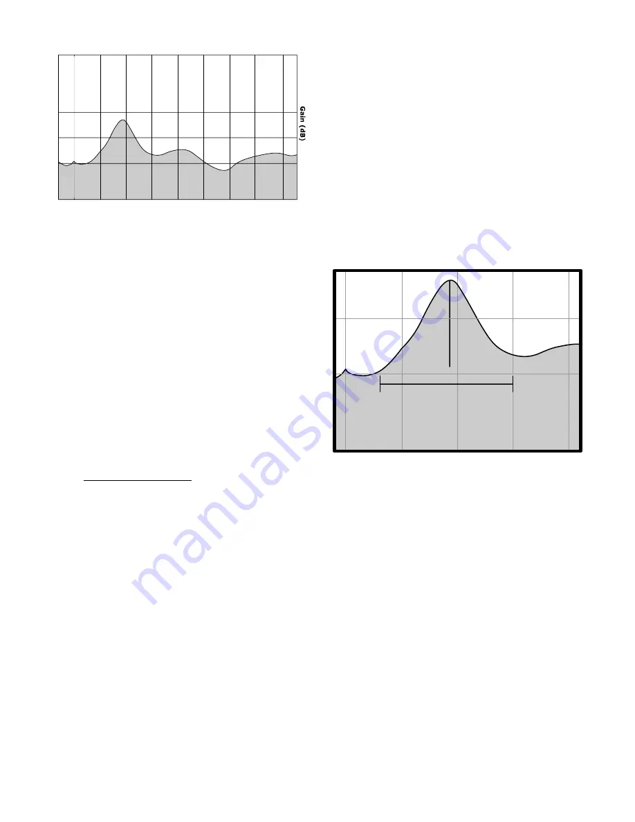
Figure 5.3
few inches can make a significant difference. It's
recommended that these tests be performed us-
ing the same speaker configuration and place-
ment you'll be using while enjoying your system,
such that the interaction between the speakers
and the subwoofer can be observed. By and
large we recommend sticking with front corner
placement if possible for the benefit of the
"corner loading" increase in output, thus using
the EQ only to flatten the response.
5.3 Advanced Parametric EQ Adjustments
And the fun begins...
For this adjustment, you will need a test disc
with frequencies from at least 20Hz to 120Hz.
Stereophile Magazine and the previously men-
tioned www.rivesaudio.com have test discs avail-
able for sale, or you can create your own disc
with a CD writer using files found on the internet.
A web search should yield suitable tones.
Once your data is plotted as shown in figures 5.2
and 5.3 , use the Frequency (A), Bandwidth (B),
and Level (C) controls (as shown in figure 5.1) to
adjust your subwoofer’s response as follows:
A) Frequency—This control allows you to set
the exact point at which you want the CENTER of
the filter to be applied. In our example above,
we want to tame the peak that is centered at just
about 45Hz, and thus set our frequency filter to
the corresponding 45Hz level.
B) Bandwidth—The bandwidth control on your
UFW-12 allows you to set the WIDTH of the filter
you want applied. This control is based on a per-
centage of a full octave above, or a doubling of
frequency. Thus, when set to 1.0, the width of
the area you’ll be cutting or boosting will be a full
Frequency (Hz)
30
50
80
73
67
79
(one) octave, corresponding to an overall width
(start to finish) of double the frequency (half
above AND below your center point). In this ex-
ample, we estimate the “beginning” of the peak
in figure 5.3 to be at about 25Hz and the “end”
of the peak at about 80Hz...a range of around
55Hz.
However, the 45Hz point is not centered in this
range. Because the EQ needs a range equidis-
tant to each side of our center frequency, set in
step 1, we have to extend our area slightly (or
move our center point...more on this later) to
fully compensate the range we require. Thus, in
this example, because we want our high point at
80Hz, or 35Hz above our 45Hz center frequency,
we also have to adjust 35Hz below our center
frequency, therefore expanding the width of our
“beginning” and “end” points to 10Hz and 80Hz
respectively (as shown in figure 5.5).
However, in this example, there is one prob-
lem...our low point is far below the actual width
of our desired curve, thus even the flat portion of
the UFW’s desired response will be attenuated.
To avoid this, we need to move our center point
up just a bit, such that it is closer to equidistant
between our “beginning” and “end” points. In
other words, if we move our center point up from
45Hz to 55Hz, our “end” point of 80Hz is now
only 25Hz above our center (instead of 35Hz),
and our “beginning” point is now 30Hz below
our center (instead of 20Hz). Because we must
be equidistant from this center frequency, our
range thus becomes 25Hz to 85Hz—much closer
to our desired value. In addition, because the
system will likely be crossed over at 80Hz, the
30
50
80
Center
(45Hz)
Desired Curve Width
25Hz
80Hz
Figure 5.4


