


6
The BeeLINK bus is a parallel bus type. Passive splitters therefore can be used, to
make a network of any shape. If many controllers or very long cables are used, it might
be necessary to add more power supplies.
Using this parallel structure each beeLINK controller receives the IR-data simultane-
ously. Every controller has its own microcomputer, living its own life.
Although some of the controllers can ‘talk’ to each other, most controllers operate fully
on their own.
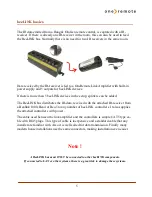
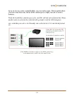
beeLINK2 installation
The beeLINK2 controller gets its power supply and control data, via the CAT5 cable
from a beeLINK amplifier. The beeBus.
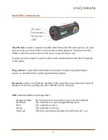
Once connected to the beeBUS the beeLINK2 controller only needs an IR-emitter to
operate the device it has been designed for. The IR-emitter emits the same IR data as
the device’s own remote control.
Emitted IR data is in fact pure light at a frequency just out of the spectrum that the human eye is able to see.
It emits short flashes of light, a bit like when sending Morse codes using a flashlight.
The emitter must be stuck on the device, nearby the De-
vices IR-receiver. It must be placed so the IR receiver in
the device is able to see the emitted light from the IR-
emitter.
The beeLINK2 controller can be placed by the device or
in another room. IR emitters are available in lengths of 1,
5 and 10 meters. Additional extension cords can be used.
An IR-emitter can be extended to more than 50 meters.
The IR-emitter can be placed inside the device, if you want to avoid having it on the
outside, as long as the IR-receiver is able to see the light from the emitter. This requires
that the device is opened and the emitter is placed inside.