NCP370GEVB
http://onsemi.com
2
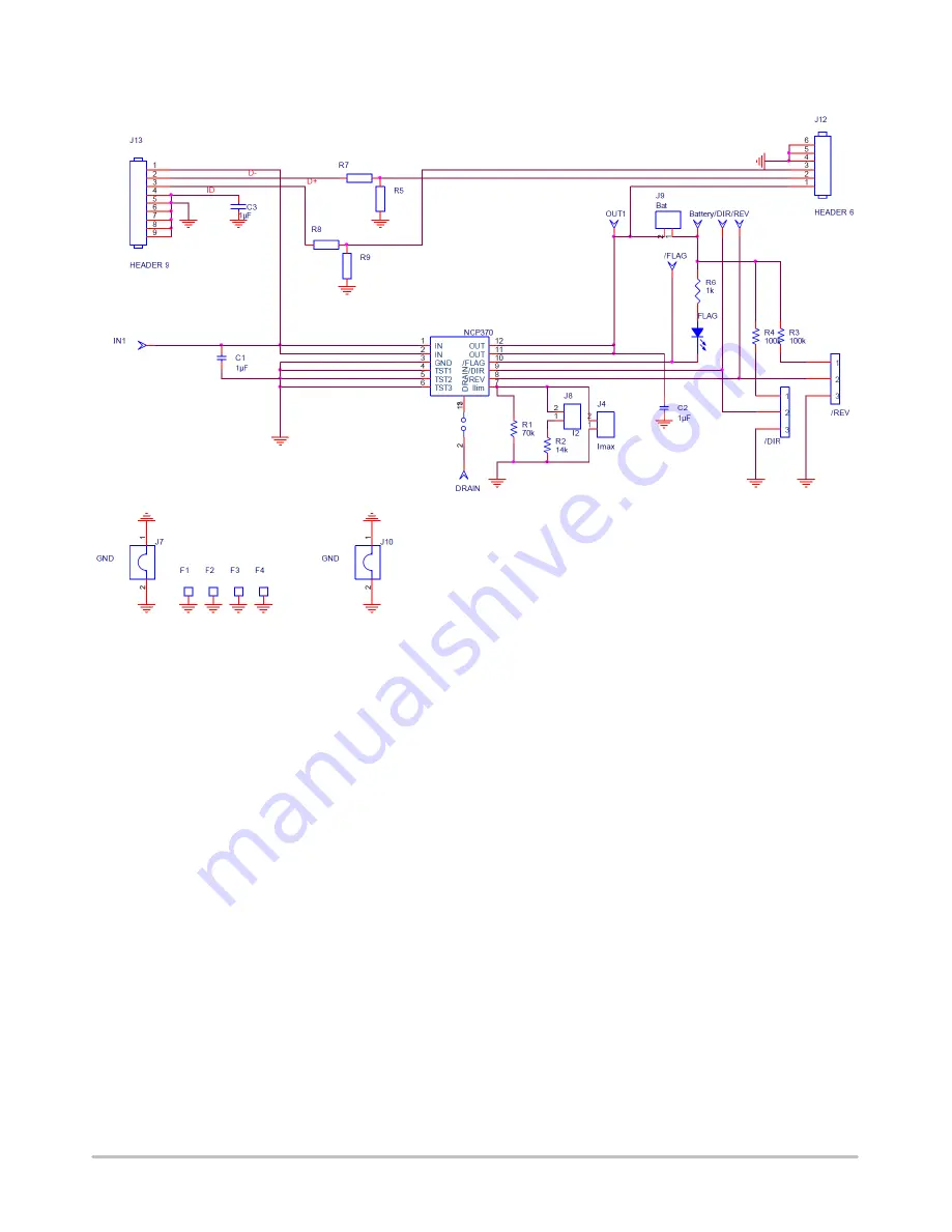
Figure 2. NCP370GEVB Board Schematic
Page 1: ...the Vout turns on 30 ms after the Vin exceeds the undervoltage threshold The second mode called the Reverse Mode allows an external accessory to be powered by the system battery or a boost converter...
Page 2: ...NCP370GEVB http onsemi com 2 Figure 2 NCP370GEVB Board Schematic...
Page 3: ...Molex WM17118 ND 4 pins USB A 1 FLAG rohm 511 1287 ND Green LED 0805 1 R6 susumu Rr08p value dct nd 1 kW CMS0603 0 5 2 R3 R4 susumu Rr08p value dct nd 100 kW CMS0603 0 5 Not mounted R5 R7 R8 R9 USB d...
Page 4: ...NCP370GEVB http onsemi com 4 PCB Figure 3 NCP370GEVB Board Layout Top View Figure 4 NCP370GEVB Board Layout Bottom View...
Page 5: ...5 CONNECTING PROCESS 1 Place REV strap and DIR strap on left side 1 logic connected to Vbat through pull up resistor 2 Let Battery strap opened 3 Connect a Battery or power supply 4 2 V on Battery tes...
Page 6: ...NCP370GEVB http onsemi com 6 4 Connect strap on lim ILIM PIN 7 SW2 2 R2 14k R1 70k SW1 IMAX...
Page 7: ...it threshold with pull down resistors connected on pin 7 SW1 SW2 IOCP 0 0 500 mA 0 1 1 A 1 0 1 5 A 1 1 1 5 A R1 70K R2 14K Disable Mode 6 Connect 10 V capability Vin Supply on IN1 test point a Set pow...
Page 8: ...ft to right 1 logic level to 0 logic level 8 Check Vout 5 V and Flag LED is still off 9 Set Vin 7 V 10 Check Flag LED on and Vout is 0 V 11 Switch REV from left to right 1 logic level to 0 logic level...
Page 9: ...as components in systems intended for surgical implant into the body or other applications intended to support or sustain life or for any other application in which the failure of the SCILLC product c...