


173
F3SJ-A
User’s Manual
Ch
apt
e
r
5
Wir
ing
Ex
amples
Input/Output Circuit and Applications
E
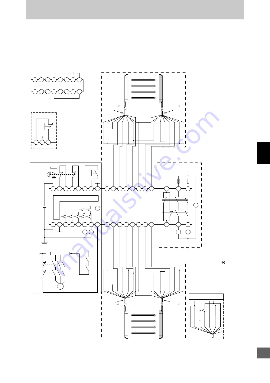
Connecting to an F3SX-E-L2R2
•Emergency stop switch can be connected
•Door switch, two hand control, single beam, or relay unit can be used in combination with F3SX
•Various settings can be changed and input/output terminals can be monitored using the setting
support software for F3SX
S1
S2
11
12
22
21
DC24V
E1
A1
T11
T12
T21
T22
Y1
Y2
Y3
DC24V
E1
A2
DC24V
DC24V
COM
0V
SSC
AS3
AS2
AS1
SS1
SS2
FB
E1
DC24V
RY1
RY2
DC24V
E1
KM1
KM2
M
RY1
RY2
15
10
12
13
14
16
9
11
2
7
5
4
3
1
8
6
12
34
24
33
11
23
AC
K1
K2
KM1
KM2
2
7
5
4
3
1
8
6
15
10
12
13
14
16
9
11
Wiring when safety light curtain
F3SJ is not used
L2 Module
Emitter
Receiver
F3SJ (1st unit)
Communication
line (+) (Grey)
Communication
line (-) (Pink)
Shiel
0V (Blue)
Open
Test input (Green)
Reset input (Yellow)
Interlock selection input (White)
+24V (Brown)
+24V (Brown)
External device monitoring
input (Red) (Note 2)
Auxiliary output 1
(Yellow) (Note 2)
Auxiliary output 2 (Red)
Safety output 1 (Green)
Safety output 2 (White)
0V (Blue)
Shield
Main Module
Control Circuit
Motor controller
(operation command)
S1
:Emergency stop switch
(direct circuit operation contact)(A165E, A22E)
S2 :Reset
switch
KM1, KM2 :Magnetic contactor
RY1, RY2 :Relay
M :3-phase
motor
E1
:24VDC power supply (S82K)
Shield
0V (Blue)
DC24V (Brown)
DC24V (Brown)
0V (Blue)
Shield
Test input (Green)
Reset input (Yellow)
Interlock selection input (White)
Open
External device monitoring
input (Red) (Note 2)
Auxiliary output 1 (Yellow)(Note 2)
Auxiliary output 2
(Red)
Safety
output 1 (Green)
Safety
output 2 (White)
Communication
line (+) (Grey)
Communication
line (-) (Pink)
F3SJ (2nd unit)
Emitter
Receiver
Shield
Test SW
0V (Blue)
Open (Red)
Test input (Green)
Reset input (Yellow)
Interlock selection input (White)
DC24V (Brown)
Wiring when F3SJ's
testing function is used
Relay Output Module
(R2 Module)
Fuse
- F3SJ settings
- Auto reset mode
- Does not use external device monitoring function
- F3SX-E-L2R settings
- Manual reset mode
- Using feedback time monitoring function
Model F39-JC A-L
cable for emitter
Model F39-JC A-D
cable for receiver
Model F39-JC A-L
cable for emitter
Model F39-JC A-D
cable for receiver
Y3
Y2
Y1
E1
DC24V
S2
Wiring for auto reset mode
Note 1 :The OFF-delay contacts (K1, K2) may instantly turns OFF due to a
circuit error occurring in the controller. Accordingly, when the
current supply to the motor is ceased before the motor stops and it
may cause a hazardous situation to the system, the example of
wiring above should correspond to the Category 2. If, however, it
may not cause a hazardous situation, the example of wiring above
should correspond to the Category 4.
Note 2 :Example when the auxiliary output is of standard setting (ON when
light interrupted).
For other than standard setting, refer to the Catalog or User's
Manual of F3SN-A/F3SH/F3SJ.
Note 3 :When the F3SJ is series-connected, or 5 or more sets are
connected to the total system of F3SX, power
must be supplied to F3SJ from external source. For details, see
documentation of F3SX.
Note 4 :Example of circuit above corresponds to the Stop Category
(EN60204-1) 1.
Note 5 :In the example of wiring above, it is necessary to change the
threshold value of feedback monitoring time in consideration for
the delay time setting value by using the function set-up software
for model F3SX (Model F3SX-CD
, sold separately).
Courtesy
of
CMA/Flodyne/Hydradyne
▪
Motion
Control
▪
Hydraulic
▪
Pneumatic
▪
Electrical
▪
Mechanical
▪
(800)
426-5480
▪
www.cmafh.com


