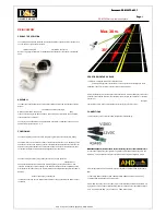
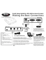
background image

No.18S065-03 


1/71 

STC-MBS2041POE / STC-MCS2041POE 
Product Specifications and User’s Guide 


GigE Vision 

Monochrome / Color CMOS PoE Camera 


STC-MBS2041POE


(20M / 

Monochrome

STC-MCS2041POE


(20M / 

Color


Product Specifications and User’s Guide 


Summary of Contents for STC-MBS2041POE

Page 1: ...71 STC MBS2041POE STC MCS2041POE Product Specifications and User s Guide GigE Vision Monochrome Color CMOS PoE Camera STC MBS2041POE 20M Monochrome STC MCS2041POE 20M Color Product Specifications and...

Page 2: ...14 5 4 Environmental Specifications 15 6 Connector Specifications 16 6 1 RJ45 Connector 16 6 2 Power and Control Signal Connector 17 Opto isolated input 20 Opto isolated output 20 Open Collector GPIO...

Page 3: ...olarity Trigger Signal 33 9 3 Edge Preset Trigger Mode 34 Timing When using rolling shutter 34 Exposure Timing with Positive Polarity Trigger Signal 35 Exposure Timing with the Negative Polarity Trigg...

Page 4: ...setting 46 10 8 Gamma correction 47 10 9 ROI Region of Interest 47 10 10 Pixel Format 48 10 11 Trigger 49 Trigger signal processing procedure 49 10 12 Image Flip 50 10 13 LUT Control 50 10 14 Defecti...

Page 5: ...d User s Guide 11 8 SoftwareSignalControl 63 11 9 CounterAndTimerControl 64 11 10 EventControl 65 11 11 UserSetControl 65 11 12 ChunkDataControl 66 11 13 ActionControl 66 11 14 FileAccessControl 67 11...

Page 6: ...ses incorrectly About Graphic symbols This symbol shows general prohibition This symbol shows completion or instruction Environment condition Warning Do not use flammable or explosiveness atmospheres...

Page 7: ...of electrification or accident caused by malfunction Do not put combustibles near the camera This will cause of fire Do not use without usage that is specified in the specifications for this camera T...

Page 8: ...ly the power that satisfies the specified in specifications for the camera The defective pixels may appear due to the sensor characteristics Use below recommend materials or equivalent materials to cl...

Page 9: ...imer in the documentation and or other materials provided with the distribution 3 The name of the author may not be used to endorse or promote products derived from this software without specific prio...

Page 10: ...1 Features GigE Interface Support PoE Power over Ethernet Small robust camera housing Maximum frame rate Full resolution 5 6 fps 20M 8bits CMOS Global Reset Shutter Rolling Shutter Up to 2 048 Defect...

Page 11: ...s than 11 2 digits Gain 0 dB 12bits 12bits Packed output Less than 44 8 digits Gain 0 dB Sensitivity 1 720 Lux 1 480 Lux Exposure Time 2 260 902 seconds to 16 777 seconds Default 178 925 902 seconds G...

Page 12: ...t is 518 902 seconds to 16 777 seconds 3 The camera operates with external power when power suppling by external power supply and PoE to camera at same time Camera Setting Environment Parameter Settin...

Page 13: ...No 18S065 03 13 71 STC MBS2041POE STC MCS2041POE Product Specifications and User s Guide 5 2 Spectral Sensitivity Characteristics STC MBS2041POE STC MCS2041POE without IR Cut Filter...

Page 14: ...tical Filter IR Cut Filter Optical Center Accuracy Positional accuracy in Horizontal and Vertical directions 0 3 mm Rotational accuracy of Horizontal and Vertical 1 5 deg Material Aluminum Alloy AC Le...

Page 15: ...85 RH No condensation Vibration 20 Hz to 200 Hz to 20 Hz 5 min cycle acceleration 10 G XYZ 3 directions 30 min each Shock Acceleration 38 G half amplitude 6 ms XYZ 3 directions 3 times each Standard...

Page 16: ...B supported NIC Network Switcher and Ethernet cable Check the setting of NIC and Network Switcher being used is 1GB transferring Green LED Yellow LED Status Green Light ON Yellow Light OFF Power ON 1G...

Page 17: ...command Pin No Signal Name IN OUT Voltage 1 POWER IN IN 10 8 to 26 4 Vdc 2 Opto isolated in Line0 IN Low Smaller than 1 0 V High 3 0 to 26 4 V Potential difference between TRG_in and Opt Isolated Com...

Page 18: ...Internal The image transferring starts signal is out 6 Sensor Read Out FVAL Frame valid HIGH state signal is out 7 Debounced Line0 Debounced Line0 signal is out 8 Debounced Line2 Debounced Line2 signa...

Page 19: ...s Guide 16 Flash Window The external light source control signal is out This signal can be used to set active time of light source for rolling shutter to acquire acceptable image Line0 Line1 Line2 Li...

Page 20: ...fications and User s Guide Opto isolated input The camera has current limiting circuit on camera The current limiting resistor does not necessary Opto isolated output It is necessary to have current l...

Page 21: ...outside of camera to keep current less than 50 mA When using as input current limiting resistor does not necessary However camera does not have current limiting circuit on camera The camera inside ci...

Page 22: ...internal processing Output signals FrameTriggerWait ExposureActive DebounceLine0 2 FramTriggerInternal SensorReadOut Timer0 Debounce External hardware trigger delay Tdelay Parameter ExposureTime on Ge...

Page 23: ...xposure Mode and Positive Edge Trigger Software trigger Trigger delay Exposure Image out Camera Internal processing Output signals FrameTriggerWait ExposureActive FramTriggerInternal SensorReadOut Tim...

Page 24: ...hoto coupler or transistor Please refers example measurement of delay in below 6 2 6 1 External Trigger Signal Delay Positive polarity trigger signal External Trigger Signal External Trigger Signal wi...

Page 25: ...trigger signal Pull up voltage Tdelay Minimum active pulse duration Pull up voltage Tdelay Minimum active pulse duration 3 3 V 8 2 seconds 6 seconds 3 3 V 47 seconds 6 seconds 12 V 4 6 seconds 3 seco...

Page 26: ...larity trigger signal Pull up voltage Tdelay Minimum active pulse duration Pull up voltage Tdelay Minimum active pulse duration 3 3 V 3 9 seconds 6 seconds 3 3 V 0 6 seconds 6 seconds 12 V 3 8 seconds...

Page 27: ...71 STC MBS2041POE STC MCS2041POE Product Specifications and User s Guide 7 Dimensions 7 1 STC MBS2041POE Unit mm 15 20 2 M3 Depth3 5 29 29 28 5 53 42 49 15 20 16 1 20 7 5 7 1 32UNF C mount 4 M3 Depth...

Page 28: ...03 28 71 STC MBS2041POE STC MCS2041POE Product Specifications and User s Guide 7 2 STC MCS2041POE Unit mm 15 20 2 M3 Depth3 5 29 29 1 32UNF C mount 28 5 53 42 49 15 20 16 4 M3 Depth3 5 1 20 2 M2 Dept...

Page 29: ...Sensor Information 8 1 Pixel Transferring Image STC MBS2041POE Monochrome Pixel m of Data mth pixel being transferred STC MCS2041POE Color Pixel m n of Data mth pixel of nth line being transferred Pi...

Page 30: ...s and User s Guide 9 Camera Operational Modes 9 1 Normal Mode Rolling shutter Exposure Image out Exposure Time Line 1 Line 2 Line N 1 Line N Line 1 Line 2 Line N 1 Line N Line 1 Line 2 Line N 1 Line N...

Page 31: ...period is high states of trigger signal In this trigger mode with negative polarity the expose starts at falling edge of trigger signal and stops at rising edge of trigger signal The expose period is...

Page 32: ...emainder 0 0 Remainder 0 1 A 2 902 seconds e g Case Trigger width 50 seconds on STC MCS2041POE CEILING 50 seconds 43 seconds 1 16279 Quotient of division 1 Remainder 0 16279 CEILING 1 1 2 T1 2 x 43 se...

Page 33: ...emainder 0 0 Remainder 0 1 A 2 902 seconds e g Case Trigger width 50 seconds on STC MCS2041POE CEILING 50 seconds 43 seconds 1 16279 Quotient of division 1 Remainder 0 16279 CEILING 1 1 2 T1 2 x 43 se...

Page 34: ...on preset exposure setting stored by camera setting communication In this trigger mode with negative polarity the expose starts at falling edge of trigger signal The exposure duration time is based o...

Page 35: ...e width trigger signal Note 2 Please refers 5 2 6 External Hardware Trigger Input Delay for more details about External hardware trigger delay Exposure Timing with the Negative Polarity Trigger signal...

Page 36: ...posure setting stored by camera setting communication In this trigger mode with negative polarity the expose starts at falling edge of trigger signal The exposure duration time is based on the preset...

Page 37: ...GenICam The details of the parameters and the functions are in the table below GenICam Parameters UserSetSelector IEnumeration Type Select Default or User Set X User Set Load or User Set Save process...

Page 38: ...ra settings put back to factory default settings Setting Procedure 1 Selects Default at User Set Selector 2 Executes User Set Load 3 Select User Set X at User Set Selector 4 Executes User Set Save Whe...

Page 39: ...al Gain Analog Gain This parameter sets analog gain Selects Analog ALL at Gain Selector sets gain at Gain GenICam Parameters GainSelector IEnumeration Type Selects control gain Analog All Analog Gain...

Page 40: ...ond 1 Range 260 902000 to 16 777 183 902000 Default 178 925 902000 ExposureAuto IEnumeration Type Auto exposure ON OFF selection 2 1 The approximate value of set value sets to camera and display it Th...

Page 41: ...ight Selection Region 0 to Region 8 AutoLuminanceWidth IInteger Type Width for selected ALC weight region Range 4 to 5 472 Default 1 802 for all regions AutoLuminanceHeight IInteger Type Height for se...

Page 42: ...Peak 50 ALC control method The ALC control with weight region 0 to 8 The weight area setting parameters are in below The brightness average and peak calculate for each weight area The target brightne...

Page 43: ...t Analog All when AGC is turned on Selection Analog All analog gain and Digital All digital gain Default Analog All Gain GainSelector IFloat Type Gain Selected gain at Gain Selector is adjusting Analo...

Page 44: ...tMin IFloat Type Minimum exposure time in second for auto shutter Range 260 902 to 16 777 215 Default 260 902 ExposureAutoLimitMax IFloat Type Maximum exposure time in second for auto shutter Range 26...

Page 45: ...e White balance control method selection Selection Off Once Continuous Preset 0 Preset 1 and Preset 2 Default Off White balance control method selection OFF The white balance with Balance Ratio settin...

Page 46: ...nceWhiteAuto RegionSelector IEnumeration Type White balance gain calculation region selection Selection Region 0 BalanceWhiteAuto Width IInteger Type Width horizontal size in pixel for white balance g...

Page 47: ...of output image in pixel Range 40 to 5 472 Default 5 472 Adjustable steps 40 Width Offset X should not exceeded maximum width Height IInteger Type Height vertical size of output image in line Range 2...

Page 48: ...llowing chart shows the available Pixel Formats on camera Output Bits Pixel Format Monochrome Camera STC MBS2041POE Color Camera STC MCS2041POE 8bits Mono8 Mono8 BayerRG8 10bits Mono10 Mono10 BayerRG1...

Page 49: ...l Action 0 Action command trigger Line 0 Hardware trigger through Line 0 Line 2 Hardware trigger through Line 2 Logic Block 0 Trigger generates by Logic Block Control Please refers Trigger signal proc...

Page 50: ...d Reverse Y GenICam Parameters ReverseY IBoolean Type Vertical flip image ON OFF selection Selection False Vertical flip is Off True Vertical flip is On Default False Vertical flip is Off 10 13 LUT Co...

Page 51: ...correction ON OFF selection Selection True On False Off Default True PixelCorrection Enabled IBoolean Type Defective pixel correction ON OFF selection for selected index Selection True On False Off De...

Page 52: ...pe Polarity of reference signal to generate Timer 0 active signal Default Rising Edge TimerValue IFloat Type Returns value for Timer 0 active signal When the timing of Timer 0 active signal is adjusti...

Page 53: ...1 Exposure Line N Exposure Active Sensor Read Out Event Exposure Start Event Frame Start Event Exposure End Event Frame End GVCP GenICam Parameters Event Selector IEnumeration Type Event notification...

Page 54: ...imer Value and Counter Value ChunkEnable IBoolean Type Enable Chunk data that was selected at Chunk Selector Selection True Enable Chunk data and False Disable Chunk data 10 18 Action Control The mult...

Page 55: ...re are more than two devices has most accurate clock in same network clock of smallest MAC address device is defined as Master Clock 2 E2E End to End Transparent Clock The camera supports E2E method T...

Page 56: ...hronized exposure for trigger mode When action command generating action command is broadcasting to each camera and camera starts exposing Synchronized exposure does not secure if action command does...

Page 57: ...r version of Standard Features Naming Convention that was used to create the device s GenICam XML DeviceManifestEntrySelector Selects the manifest entry to reference DeviceManifestXMLMajorVersion Indi...

Page 58: ...stream DeviceEventChannelCount Indicates the number of event channels supported by the device DeviceCharacterSet Character set used by the strings of the device s bootstrap registers DeviceReset Rese...

Page 59: ...pixels Height RegionSelector Height of the image provided by the device in pixels OffsetX RegionSelector Horizontal offset from the origin to the region of interest in pixels OffsetY RegionSelector Ve...

Page 60: ...internal trigger TriggerSource TriggerSelector Specifies the internal signal or physical input Line to use as the trigger source TriggerActivation TriggerSelector Specifies the activation mode of the...

Page 61: ...eight of the area determined by Auto Luminance Region Selector for auto luminance control AutoLuminancePeak Ratio of peak and average for auto luminance control BlackLevelSelector Selects which Black...

Page 62: ...T selected by LUT Selector LUTValueAll LUTSelector Accesses all the LUT coefficients in a single access without using individual LUT Index PixelCorrectionAllEnabled Enable pixel correction for all pix...

Page 63: ...ime of polling in a single bitfield UseOutputSelector Selects which bit of the User Output register will be set by User Output Value UseOutputValue UseOutputSelector Sets the value of the bit selected...

Page 64: ...terSelector Does a software reset of the selected Counter and starts it CounterValue CounterSelector Reads or writes the current value of the selected Counter TimerSelector Selects which Timer to conf...

Page 65: ...eatures related to the Frame End Event EventLine0RisingEdgeData Category that contains all the data features related to the Line0 Rising Edge Event EventLine0FallingEdgeData Category that contains all...

Page 66: ...r Selects which Exposure Time to return ChunkExposureTime ChunkExposureTimeSelector Returns the exposure time used to capture the image ChunkLineStatusAll Returns the status of all the I O lines at th...

Page 67: ...ws the exchange of data between the device file storage and the application FileAccessOffset FileSelector FileOperationSelector Controls the Offset of the mapping between the device file storage and t...

Page 68: ...h logical link to control GevMACAddress GevInterfaceSelector MAC address of the logical link GevCurrentIPConfigurationLLA GevInterfaceSelector Controls whether the Link Local Address IP configuration...

Page 69: ...cts the stream channel to control GevSCPInterfaceIndex GevStreamChannelSelector Index of the logical link to use GevSCPHostPort GevStreamChannelSelector Controls the port of the selected channel to wh...

Page 70: ...New Document 01 2019 05 14 Revised Update maximum frame rate for ROI 02 2019 05 30 Revised Revised type of GenICam parameters 03 2019 06 07 Revised Added LWIP TCP IP Licensing information GigE Vision...

Page 71: ...1 71 STC MBS2041POE STC MCS2041POE Product Specifications and User s Guide 19F Ebina Prime Tower 9 50 Chuo 2 chome Ebina city Kanagawa 243 0432 Japan TEL 81 46 236 6660 FAX 81 46 236 6661 URL http www...

Reviews: