LCD monitor
Model
FZ-M08
PRECAUTIONS ON SAFETY
Please observe the following notices that are necessary for maintaining safety:
PRECAUTIONS FOR SAFE USE
6
.
Specifications
●
General specifications
WARNING
WARNING
9
.
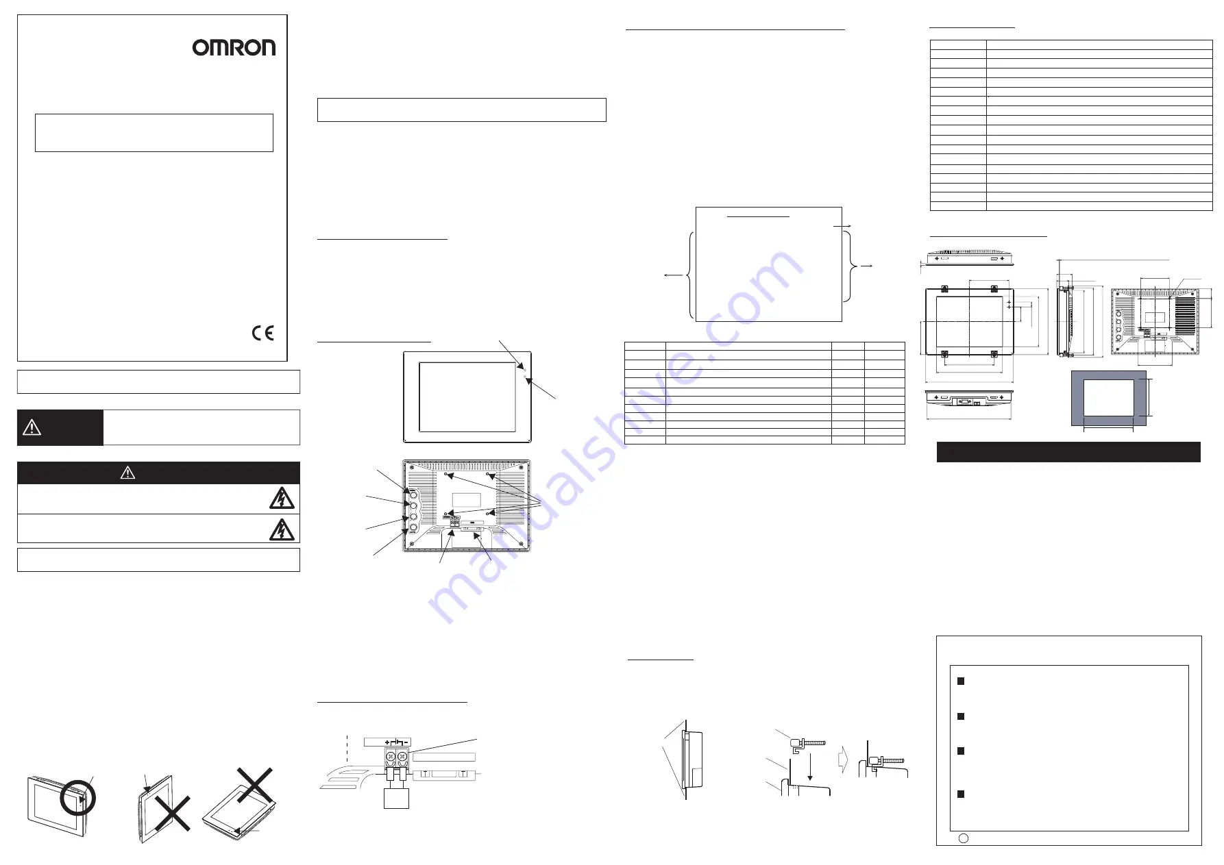
External dimensions
(Unit: mm)
(1)Lit up green when power is ON.
(2)Lit up orange while the video signal is input.
(3)Connect power unit for 24 VDC.
(4)Video input terminal (RGB)
(5)OSD operating button (MENU button)
(6)OSD operating button (+ button)
(7)OSD operating button (- button)
(8)OSD operating button (AUTO button)
(9)Mounting hole for VESA 75 mm x 75 mm
For the operating methods of respective buttons, see 4. OSD (On Screen Display) adjust
function.
3
.
Power connection terminal
M3
(Outside diameter of crimp terminal:
Dia 5.5 mm maximum)
Recommended model
OMRON Corporation-manufactured
S8VS-03024
・
Keep the power supply wires as short as possible (maximum 10 m).
・
If UL recognition is required, use a UL class
Ⅱ
power supply.
Regarding installation, do not use the VESA mounting but fix the monitor
unit using the board mounting.
Power connection terminal is located on the back of the main unit.
Connect power unit for 24 VDC.
●
Alert statements
1
.
Checking the package
Check that the following items are included in the box.
・
LCD monitor ……………………………… 1 unit
・
Instruction sheet (this sheet) ……………… 1 sheet
・
Compliance Information sheet …………… 1 sheet
・
Brackets ………………………………… 4 pieces
All possible care is taken in packing the required quantity of items. However,
in the case of a shortage, contact your dealer or any of nearby branch office
of OMRON corporation.
2
.
Component names
●
Front view
Display section
(1) LED indicator lamp (for power)
(2) LED indicator lamp
(for SYNC)
4
.
OSD (On Screen Display) adjust function
Adjust the display condition of this product by operating the adjustment menu indicated by OSD.
Operate OSD with the adjust buttons provided on the back of the monitor.
OSD menu will not start up unless a video signal is input.
Functional descriptions of each button
■
Button
・
MENU : Starts OSD operation. Decision and release of adjust items
・
+
: Adjustment of set value Upward shift of adjust item
・
−
: Adjustment of set value Downward shift of adjust item
・
AUTO
: Automatic adjustment will run if pressed when OSD is not indicated
(Phase, HPosition, VPosition)
Automatic adjustment may be disabled depending on the input signal and/
or monitor cable in use.
In such a case, users are requested to adjust the screen manually.
Set values can be reverted to their default values (setting at shipment) when the "
+
" and
"
−
" buttons are pressed simultaneously for approx. 5 seconds.
PRECAUTIONS FOR CORRECT USE
5
.
Mounting
(1)Fit the LCD monitor into a mounting
board prepared in advance.
Board
Board
●
Meaning of Signal Words
Indicates a potentially hazardous situation which, if not avoided,
will result in minor or moderate injury, or may result in serious
injury or death. Additionally there may be significant property
damage.
Do not open rear cover.
High voltage part inside may cause electric shock hazard.
Do not use this device in locations where foreign substances or water
(droplets) may enter. This may result in electric shock or fire.
■
Power supply and wiring
・
Be sure to use the product with the power supply voltage specified by this manual.
・
Use crimp terminals of the specified size. Do not simply connect the twisted ends of the wires
directly to the terminal block.
・
Use a DC power supply with safety measures against high-voltage spikes (safety extra
low-voltage circuits on the secondary side).
■
Installation environment
・
Do not use the product in environments where it may be exposed to
inflammable/explosive/corrosive gas.
・
Do not use the product outdoors or in environments exposed to direct sunlight.
・
Install the unit so that air can flow freely through its cooling vents.
・
Install the product away from high-voltage devices and motor-powered devices in order to
secure safe operation and maintenance.
・
Be sure all mounting screws are tightened securely.
・
Install the unit in a site where it will be not come into contact with water, oils or chemicals.
■
Installation method
・
To improve heat dissipation, install the product in the following orientation as shown in the
figure below.
■
Other
・
The liquid crystal panel contains stimulant inside. If an LCD panel is damaged and the liquid
substance inside comes in contact with human skin or get into an eye, immediately wash with
flowing water and consult a physician.
・
The LCD panel is a glass product. Do not hit or drop it or it may break and cause a dangerous
situation. Handle it with care.
・
Ensure you do not disassemble, deform under pressure or incinerate the main unit.
・
If you suspect an error or malfunction, stop using the unit immediately, turn OFF the power
supply, and consult your OMRON representative.
・
Dispose of this product as industrial waste.
●
A transparent seal covers the front screen of FZ-M08 for protection. It may impair your
screen visibility if used with it on. Peel it off before using.
●
Although the LCD panel is manufactured with precision technology, there are cases where
some products are shipped with traces of pixel defects. This is due to the structural reason of
LCD and is not a failure.
●
Wire the Power Supply Unit independently of other devices. Keep the power supply wires as
short as possible.
●
Turn OFF the power and take appropriate safety precautions before conducting maintenance work.
When soiled, wipe the unit with a piece of soft cloth. Use an air brush to clean the dirt off the display
panel screen. Do not use benzene, thinner or other solvents for cleaning.
●
Use FZ-VM for monitor cable.
24 VDC
RGB
Power
supply
DC24V
●
Rear
●
In the case of panel mounting
●
In the case of VESA mounting
(5) MENU button
(6) + button
(7) - button
(4) Video input (RGB)
(9) VESA mounting
hole (M4)
(3) Power connection terminal
(8) AUTO button
OSD function
OSD screen will appear when the setting item selector button (MENU) is pressed.
(Example of OSD screen)
Setting item
Monitor Setting
Set value
Resolution
※
Adjustment range of transverse and longitudinal directions of the position varies
by the input resolution. The above table shows the case of XGA.
Adjust item
(Example of operation)
・
When desiring to adjust flickering and display position by auto adjust function.
1. Press the "AUTO" button when OSD screen is not shown.
2. "Adjusting ..." message appears during automatic adjustment.
3. "AUTO Adjust OK" or "AUTO Adjust error" appears several seconds later.
4. In the case of an error, select an item to adjust and make adjustment manually.
・
When desiring to adjust the screen position (transverse direction) manually.
1.Press the "MENU" button to have OSD displayed on the screen.
2. Use the "+" and "-" buttons to move the gray cursor through the settings items.
3. Clicking on the "MENU" button when the cursor is aligned with the "HPosition" will change
the cursor to yellow and switch to the Value Adjustment Mode. Use the "+" and "-" buttons to
achieve the optimum positions while looking at the screen.
4.The setting will end if no button is pressed for 10 seconds or longer and then the set values will
be memorized.
This product can be mounted on to the arms conforming to the VESA standard.
Fix the unit using the VESA mounting holes (M4) of 75 mm x 75 mm pitch on the back of the main
unit. For details about mounting, refer to the instruction manual of the arm.
Item
Specifications
Power supply voltage
Current consumption
Vibration resistance
Ambient temperature
Ambient humidity
Degree of protection
Material
Weight
0.7 A maximum
10 to 150 Hz at a single-amplitude of 0.1 mm (maximum acceleration: 15 m/s
2
), 10 times for 8 minutes each in 3 directions
Operating: 0 to 50°C, Storage: -20 to 60°C
Operating and storage: 20 to 85% RH (No condensation)
21.6 to 26.4 VDC
IEC60529 IP20
Approx. 1.0 kg
Front panel: PC, case: PC/PBT, buttons: ABS
Video input signal 1 channel of analog RGB video input
Screen size
Diagonal 21.3 cm, 8.4 type equivalent
1024 (vertical) x 768 (horizontal) pixels
16,700,000 colors (8 bit/color)
500 cd/m
2
600 : 1
Left and right: each 80° upward: 60° downward: 80° (Contrast ratio 10:1 minimum)
Edge light system, White LEDs
Pixel count
Display colors
Luminance
Contrast ratio
Angle of visibility
Back light
Between the group of external DC terminals and the ground terminal: 840 VAC 50/60 Hz
Dielectric strength
LED indicator
lamp
LED indicator lamp
LED indicator lamp
Do not install in this orientation.
(2)Brackets at 4 locations on the top and bottom
sides of the main unit Hook the protrusions
of the brackets on to the holes for installation,
and turn the screws to fasten.
Main unit
Mounting brackets
161.5
Panel cut drawing
+
0.5
−
0mm
(103.5)
(130)
(172)
230
(85.5)
(38)
(12.5)
(129.4)
171
(90)
75
4-M4
75
26
(31.5)
40
Mountable board thickiness:1.6 to 4.8
(173.4)
(185)
161
220
(6)
INSTRUCTION SHEET
Thank you for selecting OMRON product. This sheet pri-
marily describes precautions required in installing and
operating the product.
Before operating the product, read the sheet thoroughly to
acquire sufficient knowledge of the product. For your con-
venience, keep the sheet at your disposal.
© OMRON Corporation 2006 All Rights Reserved.
Contrast
HPosition
VPosition
0
〜
255
50
126
128
128
0
78〜178(※)
106〜150(※)
0
〜
255
0
〜
124
78
〜
178
50
ContrastGrn
ContrastRed
Phase
HTotal
0
〜
255
50
ContrastBlu
0
〜
255
50
BackLight
0
〜
31
31
AutoColor
−
−
Exit
Adjusts the screen contrast.
Adjusts screen display position in transverse direction.
Adjusts screen display position in longitudinal direction.
Adjusts the screen contrast of green.
Adjusts the screen contrast of red.
Adjusts bleeding and flickering of characters in the screen.
Adjusts until strip flickering in longitudinal direction is eliminated.
Adjusts the screen contrast of blue.
Adjusts brightness of the screen.
Automatically adjusts contrast of the screen.
Saves the set values and ends OSD.
−
−
Adjust item
Descriptions
Range of adjustment Defaults
XGA(VESA)
60Hz
Contrast
50
HPosition
126
VPosition
128
HTotal
128
Phase
0
ContrastRed
50
ContrastGrn 50
ContrastBlu 50
BackLight
31
AutoColor
Exit
NOTICE:
This product meets CISPR11 class A. The intended use of this product is in an
industrial environment only.
TRACEABILITY INFORMATION:
Importer in EU
Omron Europe B.V.
Wegalaan 67-69
2132 JD Hoofddorp,
The Netherlands
Manufacturer
Omron Corporation,
Shiokoji Horikawa, Shimogyo-ku,
Kyoto, 600-8530 JAPAN
Suitability for Use
s
Omron Companies shall not be responsible for conformity with any standards,
codes or regulations which apply to the combination of the Product in the
Buyer’s application or use of the Product. At Buyer’s request, Omron will
provide applicable third party certification documents identifying ratings and
limitations of use which apply to the Product. This information by itself is not
sufficient for a complete determination of the suitability of the Product in
combination with the end product, machine, system, or other application or
use. Buyer shall be solely responsible for determining appropriateness of the
particular Product with respect to Buyer’s application, product or system.
Buyer shall take application responsibility in all cases.
NEVER USE THE PRODUCT FOR AN APPLICATION INVOLVING
SERIOUS RISK TO LIFE OR PROPERTY WITHOUT ENSURING THAT THE
SYSTEM AS A WHOLE HAS BEEN DESIGNED TO ADDRESS THE RISKS,
AND THAT THE OMRON PRODUCT(S) IS PROPERLY RATED AND
INSTALLED FOR THE INTENDED USE WITHIN THE OVERALL
EQUIPMENT OR SYSTEM.
See also Product catalog for Warranty and Limitation of Liability.
Oct, 2014
D
OMRON Corporation
Industrial Automation Company
Contact: www.ia.omron.com
Tokyo, JAPAN
OMRON ELECTRONICS LLC
2895 Greenspoint Parkway, Suite 200
Hoffman Estates, IL 60169 U.S.A.
Tel: (1) 847-843-7900/Fax: (1) 847-843-7787
OMRON ASIA PACIFIC PTE. LTD.
No. 438A Alexandra Road # 05-05/08 (Lobby 2),
Alexandra Technopark,
Singapore 119967
Tel: (65) 6835-3011/Fax: (65) 6835-2711
OMRON (CHINA) CO., LTD.
Room 2211, Bank of China Tower,
200 Yin Cheng Zhong Road,
PuDong New Area, Shanghai, 200120, China
Tel: (86) 21-5037-2222/Fax: (86) 21-5037-2200
OMRON EUROPE B.V.
Sensor Business Unit
Carl-Benz-Str. 4, D-71154 Nufringen, Germany
Tel: (49) 7032-811-0/Fax: (49) 7032-811-199
Regional Headquarters