

Suitability for Use
Omron Companies shall not be responsible for conformity with any standards, codes or
regulations which apply to the combination of the Product in the Buyer’s application or
use of the Product. At Buyer’s request, Omron will provide applicable third party
certification documents identifying ratings and limitations of use which apply to the
Product. This information by itself is not sufficient for a complete determination of the
suitability of the Product in combination with the end product, machine, system, or other
application or use. Buyer shall be solely responsible for determining appropriateness of
the particular Product with respect to Buyer’s application, product or system.
Buyer shall take application responsibility in all cases.
NEVER USE THE PRODUCT FOR AN APPLICATION INVOLVING SERIOUS RISK
TO LIFE OR PROPERTY OR IN LARGE QUANTITIES WITHOUT ENSURING THAT
THE SYSTEM AS A WHOLE HAS BEEN DESIGNED TO ADDRESS THE RISKS, AND
THAT THE OMRON PRODUCT(S) IS PROPERLY RATED AND INSTALLED FOR THE
INTENDED USE WITHIN THE OVERALL EQUIPMENT OR SYSTEM.
OMRON Corporation
(Manufacturer)
Contact: www.ia.omron.com
Regional Headquarters
Shiokoji Horikawa, Shimogyo-ku, Kyoto, 600-8530 JAPAN
OMRON EUROPE B.V. (Importer in EU)
Wegalaan 67-69, 2132 JD Hoofddorp
The Netherlands
Tel: (31)2356-81-300/Fax: (31)2356-81-388
OMRON ELECTRONICS LLC
2895 Greenspoint Parkway, Suite 200
Hoffman Estates, IL 60169 U.S.A.
Tel: (1) 847-843-7900/Fax: (1) 847-843-7787
OMRON ASIA PACIFIC PTE. LTD.
No. 438A Alexandra Road # 05-05/08 (Lobby 2),
Alexandra Technopark,
Singapore 119967
Tel: (65) 6835-3011/Fax: (65) 6835-2711
OMRON (CHINA) CO., LTD.
Room 2211, Bank of China Tower,
200 Yin Cheng Zhong Road,
PuDong New Area, Shanghai, 200120, China
Tel: (86) 21-5037-2222/Fax: (86) 21-5037-2200
The application examples shown are suggestions. They however do not release the user from carefully checking whether the Safety door switch and its
set-up are suitable for the individual application.
The power supply for the safety door switch must provide protection against permanent overvoltage. To that effect, stabilized PELV supply units must be
used. The safety outputs can be directly integrated in the safety circuit of the control system. For applications of PL e / safety category 4 in accordance
with ISO 13849-1, the safety outputs of the safety door switch or safety door switch of the chain must be connected to a safety controller or safety relay
unit of the same Safety Category. Protection is not required when pilot wires are laid. The cables however must be separated from the supply and energy
cables. If the safety door switch is wired to relays or to non-safety relevant control components, a new risk analysis must be carried out.
If the safety door switch is connected to the safety input of a safety controller or safety relay unit, the controller must have a dual-channel monitoring time
of at least 100 ms and the accepted test pulse duration of at least 1 ms. Also, the cross-wire-short monitoring function must be disabled. Typically, a
switch-off time of 250 μs is reached with a 30-m connecting cable. The switch-off time of the safety door switch is additionally extended depending on the
cable length and the capacity of the cable used.
Note: Configuration of the safety controller
For the recommended safety controller, refer to the catalog of this product.
Individually coded safety door switches and actuators will require the
following teach-in procedure:
1. Keep the actuator away from the detection range and switch the safety
door switch's voltage supply off and back on.
2. Introduce the actuator in the detection range. The teach-in procedure is
signalled at the safety door switch, red LED on, yellow LED flashes (1 Hz).
3. After 10 seconds, the yellow LED gives brief cyclic flashes (3 Hz). Switch
off the supply voltage of the safety door switch. (If the voltage is not
switched off within 5 minutes, the safety door switch cancels the teach-in
procedure and signals a false actuator by 5 red flashes).
4. Switch the supply voltage back on. The actuator must be detected once
more in order to activate the taught actuator code. In this way, the
activated code is definitively saved.
For ordering suffix D41D-1, the executed allocation of safety door switch
and actuator is irreversible.
For ordering suffix D41D-2, the teach-in procedure for a new actuator can be
repeated an unlimited number of times. When a new actuator is taught, the
code, which was applicable until that moment, becomes invalid. Subsequent
to that, the safety outputs will be disabled for ten minutes, thus providing for
an increased protection against intentional tampering.
The green LED will flash until the expiration of the time (10 minutes) of the
enabling inhibit and the detection of the new actuator.
In case of power failure during the lapse of time, the 10-minutes tampering
protection time will restart.
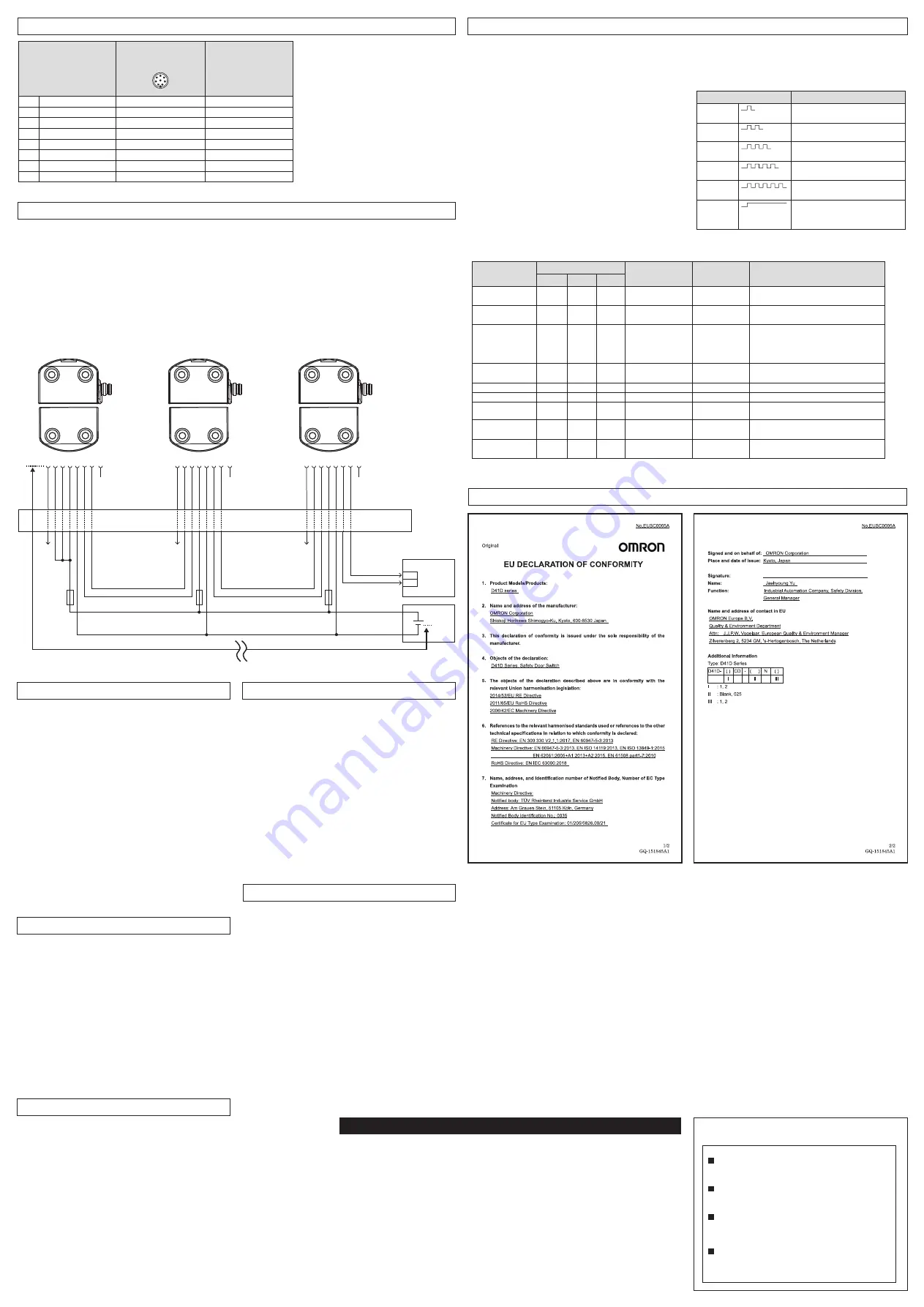
Connection
Wiring Examples
Teaching
The safety outputs can be connected to the safety circuit of the control
system. The opening of a guard door, i.e. the actuator is removed out of
the active zone of the safety door switch, will immediately disable the
safety outputs of the safety door switch. (For operating distances, refer to
Ratings and Specifications.)
Any error that does not immediately affect the functionality of the safety
door switch (e.g. too high ambient temperature, interference potential at
the safety outputs, cross-wire short) will lead to a warning message,
disabling of the auxiliary output and a delayed shutdown of the safety
outputs. (Refer to Troubleshooting.)
The safety outputs are disabled if the error warning is active for 30
minutes. The signal combination, auxiliary output disabled and safety
channels still enabled, can be used to stop the production process in a
controlled manner.
After fault rectification, the error message is reset by opening and
reclosing the corresponding guard door. The safety outputs enable and
allow a restart.
Operating Principle
Functional testing
The safety function of the safety components must be tested. The following
conditions must be previously checked and met:
1. Fitting of the safety door switch and the actuator.
2. Fitting and integrity of the power cable.
3. The system is free of dirt and soiling (in particular metal chips).
Maintenance
Maintenance frequency
SIL3 / PLe at least once a month
SIL2 / PLd at least once a year
(Daily inspection)
•
For each guard door, check that the machine stops when the guard door
opens.
(Inspection every 6 months)
1. Check the fitting and integrity of the safety door switch, the actuator and
the cable.
2. Remove possible metal chips.
3. Check that the cable is connected correctly and there is no problem.
Commission, Set-up and Maintenance
Disassembly
The product must be disassembled in a de-energized condition only.
Disposal
The product must be disposed of in an appropriate manner in
accordance with the national prescriptions and legislations.
Disassembly and Disposal
Declaration of Conformity
Operating principle of the diagnostic LEDs
The safety door switch indicates the operating condition and faults by
means of three-color LEDs located in the lateral surfaces of the safety
door switch.
The green LED indicates that the safety door switch is ready for
operation. The supply voltage is on and all safety inputs are present.
Flashing (1 Hz) of the green LED signals that a voltage is missing on one
or both of the safety inputs (X1 and/or X2).
The yellow LED always signals the presence of an actuator within range.
If the actuator is operating near the limit of the differential travel range of
the safety door switch, the LED is flashing.
The flashing can be used to prematurely detect variations in the clearance
between the safety door switch and the actuator (e.g. sagging of a guard
door). The safety door switch must be adjusted before the distance to the
actuator increases and before the safety outputs are disabled, thus stopping
the machine. If an error is detected, the red LED will be activated.
Operating principle of the auxiliary output
An auxiliary output additionally indicates the operating condition (refer to
Table 1). The auxiliary output OUT can be used for central visualization or
control functions, e.g. in a PLC. It indicates the switching condition as
shown in Table 1.
Diagnostic Functions
Error
Errors, which no longer guarantee the function of the safety door switch (internal
errors) cause the safety outputs to be disabled within the risk time.
After the rectification of the error, the error message is reset by opening
the corresponding guard door.
Error warning
The auxiliary output can also be used to detect clearance variations between
the safety door switch and the actuator in the same way as the yellow LED.
An active fault is visualized by the red LED and causes the auxiliary output to
be disabled. The safety outputs are disabled after a maximum of 30 minutes if
the fault is not rectified. This signal combination, auxiliary output disabled and
safety channels still enabled, can be used to stop the production process in a
controlled manner.
Troubleshooting
Function
Pin assignment of
connector plug
M8/M12, 8-pole, A-coded
5
8
4
3
2
1
7
6
Color code of the OMRON’s
connector
(M8/M12 connector cable)
M8: D41D-8P5-CFM8-7**M
M12: D41L-8P5-CFM12-9**M
A1
U
e
1
WHITE
X1
Safety input 1
Note: 1. When using an OMRON cable, the tightening torque of the connector is 1 N•m
2
BROWN
A2
GND
3
GREEN
Y1
Safety output 1
4
YELLOW
OUT
Auxiliary output
5
GRAY
X2
Safety input 2
6
PINK
Y2
Safety output 2
7
BLUE
IN
without function
8
RED
*1. Referred to as a safety PLC.
Note: 1. Configuration of the safety
For the recommended safety controller, refer to the product catalog of this product.
LED indication (red)
Error cause
1 flash
pulse
Error output Y1
2 flash
pulses
Error output Y2
3 flash
pulses
Cross-wire short between Y1 and Y2
4 flash
pulses
Ambient temperature too high
5 flash
pulses
Incorrect or defective actuator
Continuous
red
Internal fault,
with yellow flashing teaching
procedure
Table 1: Diagnostic information for safety door switch with auxiliary output
Switch function
LEDs
Auxiliary output
Safety outputs
Note
Green
Red
Yellow
Y1, Y2
Supply voltage
On
Off
Off
0 V
0 V
Voltage on, no evaluation of the voltage
quality
Actuated
On
Off
On
24 V
24 V
The yellow LED always signals the presence
of an actuator within range.
Actuated in limit
area
On
Off
Flashes
(1Hz)
24 V
pulsed
24 V
Error warning,
switch actuated
Off
Flashes
On
0 V
24 V
After 30 minutes if the error is not rectified
Error
Off
Flashes
On
0 V
0 V
Refer to table with flash codes
Teach actuator
Off
On
Flashes
0 V
0 V
Safety door switch in teaching mode
Tampering protection
time (*1)
Flashes
Off
Off
0 V
0 V
10 minutes pause after re-teaching
Error in input circuit
*1. Refer to Teaching.
X1 and/or X2
Flashes
(1Hz)
Off
Off
0 V
0 V
Example: door open; a door in the safety
circuit upstream is also open.
Error in input circuit
X1 and/or X2
Flashes
(1Hz)
Off
On
24 V
0 V
Example: door closed, a door in the safety
circuit upstream is open.
D41D series connection example
The safety door switch must be adjusted
before the distance to the actuator increases
and before the safety outputs are disabled,
thus stopping the machine.
1 3
2
5
6
8
X1
4
Y1
X2
7
Y2
OUT
A1 A2
1 3
2
5
6
8
X1
4
Y1
X2
7
Y2
OUT
A1 A2
1 3
2
5
6
8
X1
4
Y1
X2
7
Y2
OUT
A1 A2
Nth D41D
2st D41D
1st D41D
Terminal block,
etc.
Safety outputs
between switch and power supply
S-PLC(*1)/PLC
S-PLC(*1)/PLC
S-PLC(*1)/PLC
IN1
IN2
24 VDC
GND
Safety
Controller


