154
Analog Input Functions
Section 7-9
7-9
Analog Input Functions
7-9-1
Applicable Models
7-9-2
Overview
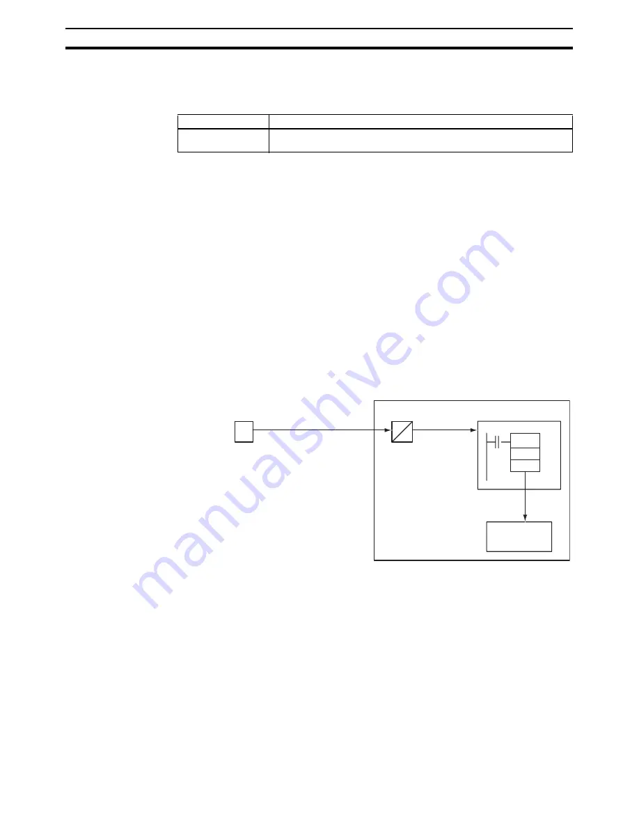
This unit executes high-speed input of analog input signals (A/D conversion
time: 50
m
s).
One of five signal types for analog inputs,
-
10 to +10 V, 0 to 10 V, 0 to 5 V, 1 to
5 V, and 4 to 20 mA can be selected.
Analog input values are stored in AR 02 of the auxiliary memory bits on the
unit. An analog input value at END refresh is stored as the input value. Addi-
tionally, analog input values can be compensated.
Using PRV instruction enables the unit to acquire the latest analog input value
through immediate refresh method. With this function, inputting analog signals
from a pressure sensor, position meter, or sensors that require high-speed
input processing such as a displacement sensor/end-measuring sensor real-
izes pressure control, tension control, or control involving mechanical mea-
surement (distortion/thickness/length) with comparatively lower cost and
ease.
Note
The analog input responsiveness of the CS1W-HCA12-V1 has been set com-
paratively higher for speeding up the processing. Because of this, the distor-
tion of input signals caused by external disturbance may be detected
sometimes. When using the unit in a place with a lot of noise, make sure to
take measures against it. In addition, when using the analog input value of the
unit, take measures against it also in the ladder program by executing the
AVG instruction with END refresh method to provide a filtering process, etc.
Model numbers
Functions
CS1W-HCA12-V1
12 contact inputs, 8 contact outputs, 1 analog input, 1 pulse input, 2 analog
outputs
I/O memory
User program
PRV
D
A
Customizable Counter Unit
CS1W-HCA12-V1
One of five signal types
for analog inputs,
−
10 to
+10 V, 0 to 10 V, 0 to 5 V,
1 to 5 V, and 4 to 20 mA
can be selected.
Immediate
refresh
Sensors
(pressure, displacement, etc.)
Store the data
when instruction
is executed.
High speed input
(A/D conversion time:
0.05 ms)
Summary of Contents for CS1W-HCA12-V1
Page 2: ......
Page 6: ...vi...
Page 20: ...xx Conformance to EC Directives 7...
Page 38: ...18 Models and System Configurations Section 1 2...
Page 78: ...58 Fail safe Circuits Section 3 5...
Page 138: ...118 AR Area Section 6 4...
Page 204: ...184 Improved Instructions Section 7 14...
Page 222: ...202 Cycle Time Section 8 3...
Page 240: ...220 Troubleshooting Flowcharts Section 9 5...
Page 244: ...224 Precautions when Using the CX Programmer Appendix A...
Page 252: ......
Page 253: ......


