


Physical layout of the unit
Section 2-1
11
Any unit number in the setting range is allowed as long as it has not been set
on another Special I/O Unit connected to the PLC. If the same unit number is
used for the C200HW-PRM21 and another Special I/O Unit, an I/O Unit Over
error will occur in the PLC and it will not be possible to start up the
PROFIBUS-DP Network.
Note
Always turn OFF the power to the PLC before changing the unit number
setting. The Unit only reads the unit number setting during the initialisation
after power-up, so not after a software reset.
Use a small flat-blade screwdriver to turn the rotary switch; be careful not to
damage the switch.
2-1-3
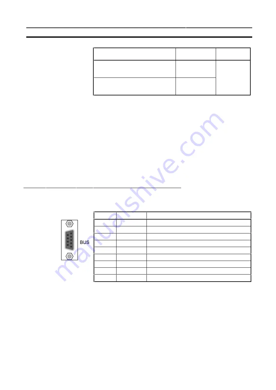
BUS Connector
The fieldbus connector is a 9-pin female sub-D connector, as recommended
by the PROFIBUS standard EN 50170.
The signals DGND and VP are used internally to power the bus terminator
(see section 2-1-5).
The signal RTS (TTL signal) is meant for the direction control of repeaters if
repeaters without self control capability are used.
The PROFIBUS standard defines 24 V remote powering signals for pin 2 and
pin 7. These signals are optional and have not been implemented in this Unit.
CPU Unit models
Unit number
setting range
Setting
method
C200HS, C200HE,
C200HG-CPU3[ ]-E/CPU4[ ]-E,
C200HX-CPU3[ ]-E/CPU4[ ]-E
0 to 9
Single-digit
hexadecimal
C200HG-CPU5[ ]-E/CPU6[ ]-E,
C200HX-CPU5[ ] -E/CPU6[ ]-E
Cs1-series
0 to F
Pin No.
Signal
Description
1
Shield
Shield / protective ground
2
-
-
3
B-line
Data signal
4
RTS
Control signal for repeaters (direction control) (TTL)
5
DGND
Data ground
6
VP
Supply voltage of the terminator resistance (5V)
7
-
-
8
A-line
Data signal
9
-
-
Summary of Contents for C200HW-PRM21
Page 1: ...C200HW PRM21 PROFIBUS DP Master Unit OPERATION MANUAL Cat No W349 E2 2...
Page 2: ......
Page 3: ......
Page 4: ......
Page 5: ...C200HW PRM21 PROFIBUS DP Master Unit Operation Manual Produced May 2000...
Page 6: ...iv...
Page 8: ...vi...
Page 12: ...x...
Page 66: ...Debug mode Section 4 4 50...
Page 98: ...Messages Section 6 4 82...
Page 108: ...Maintenance Section 7 3 92...
Page 110: ...94...
Page 112: ...96...
Page 116: ...100...
Page 120: ...104...
Page 124: ......


