background image


12 

 EN 

2

  Safety Instructions


CAUTION! 


Keep this device away from rain and moisture! 


CAUTION! 


Be  careful  with  your  operations.  With  a  dangerous  voltage  you  can  suffer  a  dangerous  electric 
shock when touching the wires!


This  device  has  left  our  premises  in  absolutely  perfect  condition.  In  order  to  maintain  this  condition  and  to 
ensure a safe operation, it is absolutely necessary for the user to follow the safety instructions and warning 
notes written in this user manual. 


Damages caused by the disregard of this user manual are not subject to warranty. The dealer will not 
accept liability for any resulting defects or problems. 


Intended Use 
• 

This device is used to mix line and phone signal 
sources. It has been specially designed for DJs. 

Unpacking 
• 

Please  make  sure  that  there  are  no  obvious 
transport  damages.  Should  you  notice  any 
damages,  do  not  take  the  device  into  operation 
and immediately consult your local dealer. 

• 

Save  the  package  and  all  packing  materials.  In 
the  event  that  a  fixture  must  be  returned  to  the 
factory, it is important that the fixture be returned 
in the original factory box and packing. 

Protection Class 
• 

This  device  falls  under  protection  class  I.  The 
power  plug  must  only  be  plugged  into  a 
protection  class  I  outlet.  The  voltage  and 
frequency  must  exactly  be  the  same  as  stated 
on  the  device.  Wrong  voltages  or  power  outlets 
can  lead  to  the  destruction  of  the  device  and  to 
mortal electrical shock.  

Power Cord 
• 

Always  plug  in  the  power  plug  least.  The  power 
plug  must  always  be  inserted  without  force. 
Make sure that the plug is tightly connected with 
the outlet.  

• 

Never let the power cord come into contact with 
other  cables!  Handle  the  power  cord  and  all 
connections  with  the  mains  with  particular 
caution!  Never  touch  them  with  wet  hands,  as 
this could lead to mortal electrical shock.  

• 

Never  modify,  bend,  strain  mechanically,  put 
pressure  on,  pull  or  heat  up  the  power  cord. 
Never  operate  next  to  sources  of  heat  or  cold. 
Disregard can lead to power cord damages, fire 
or mortal electrical shock.  

• 

The cable insert or the female part in the device 
must  never  be  strained.  There  must  always  be 
sufficient  cable  to  the  device.  Otherwise,  the 
cable  may  be  damaged  which  may  lead  to 
mortal damage.  

• 

Make sure that the power cord is never crimped 
or  damaged  by  sharp  edges.  Check  the  device 
and the power cord from time to time. 


The  occupation  of  the  connection  cables  is  as 
follows: 


Cable 

Pin 

International 

Brown 

Live 

Blue 

Neutral 

Yellow/Green  Earth 


The earth has to be connected! If the device will 
be  directly  connected  with  the  local  power 
supply  network,  a  disconnection  switch  with  a 
minimum  opening  of  3 mm  at  every  pole  has  to 
be  included  in  the  permanent  electrical 
installation.  The  device  must  only  be  connected 
with  an  electric  installation  carried  out  in 
compliance  with the IEC standards. The electric 
installation  must  be  equipped  with  a  Residual 
Current Device.  

Liquids 
• 

There  must  never  enter  any  liquid  into  power 
outlets,  extension  cords  or  any  holes  in  the 
housing of the device. If you suppose that also a 
minimal  amount  of  liquid  may  have  entered  the 
device,  it  must  immediately  be  disconnected. 
This  is  also  valid,  if  the  device  was  exposed  to 
high  humidity.  Also  if  the  device  is  still  running, 
the device must be checked by a specialist if the 
liquid  has  reduced  any  insulation.  Reduced 
insulation can cause mortal electrical shock. 

Foreign Objects 
• 

There  must  never  be  any  objects  entering  into 
the  device.  This  is  especially  valid  for  metal 
parts.  If  any  metal  parts  like  staples  or  coarse 
metal  chips  enter  into  the  device,  the  device 
must 

be 

taken 

out 

of 

operation 

and 

disconnected  immediately.  Malfunction  or  short-
circuits caused by metal parts may cause mortal 
injuries.


Summary of Contents for TRM-422

Page 1: ...1 DE ...

Page 2: ...e auf dem Gerät angebrachten Sicherheitshinweise Diese Bedienungsanleitung gilt für die Artikelnummer 10355931 Bitte bewahren Sie dieses Dokument für weiteren Gebrauch auf und geben Sie es ggf an nachfolgende Besitzer weiter Produktmerkmale Klassischer Rotary Mixer mit 4 2 Eingangskanälen und integriertem Frequenzisolator für DJs Hochwertige Bauteile garantieren lange und hervorragende Klangeigens...

Page 3: ...en ziehen erhitzen und nicht in die Nähe von Hitze oder Kältequellen bringen Bei Missachtung kann es zu Beschädigungen der Netzleitung zu Brand oder zu tödlichen Stromschlägen kommen Die Kabeleinführung oder die Kupplung am Gerät dürfen nicht durch Zug belastet werden Es muss stets eine ausreichende Kabellänge zum Gerät hin vorhanden sein Andernfalls kann das Kabel beschädigt werden was zu tödlich...

Page 4: ...assen Sie das Gerät nicht von Personen bedienen die sich nicht mit dem Gerät auskennen Wenn Geräte nicht mehr korrekt funktionieren ist das meist das Ergebnis von unsachgemäßer Bedienung Bevor das Gerät eingeschaltet wird müssen alle Fader und Lautstärkeregler auf Null oder auf Minimum gestellt werden Endstufen immer zuletzt einschalten und zuerst ausschalten Schließen Sie das Gerät nur im ausgesc...

Page 5: ...5 DE 3 Bedienelemente und Anschlüsse Rückseite Oberseite Vorderseite ...

Page 6: ...Schalter 37 wird das Effektsignal auf die Mastersumme gegeben Hinweis Werden diese Anschlüsse nicht genutzt dient das Jumperkabel zur Vermeidung von Signalausfällen bei versehentlicher Betätigung des Schalters 37 für den Effektweg 8 Eingänge LINE 1 bis 7 bzw PHONO 1 bis 4 Unsymmetrische Stereo Eingänge mit Cinch Buchsen für Kanal 1 bis 4 zum Anschluss von Geräten mit Line Pegel wie CD Player oder ...

Page 7: ...der 39 In der Position A wird der Kanal auf die linke Seite des Crossfaders geschaltet in der Position B auf die rechte Seite und in der Position THRU auf die Mastersumme Werden alle Eingangskanäle auf die Mastersumme geschaltet ist der Crossfader deaktiviert und das gewünschte Lautstärkeverhältnis lässt sich mit den Kanalreglern einstellen 22 Taste CUE mit LED Bei gedrückter Taste wird das Kanals...

Page 8: ... Tonmaterials genutzt werden 39 Crossfader Zum Überblenden zwischen zwei der Kanäle 1 bis 4 die mit den Zuordnungsschaltern 21 angewählt werden Der Crossfader wird deaktiviert wenn alle Schalter auf THRU stehen 40 Umschalter CUE SPLIT Definiert den Abhörmodus am Kopfhörerausgang 47 Im Modus SPLIT Schalter nach rechts gelegt liegt der Prefader Pegel mono auf der einen Seite des Kopfhörers an und da...

Page 9: ...inke mono Rot Spitze Schwarz Ring Schirm unverb Rot Spitze Schirm Schaft 3 5 mm Klinke stereo Rot Spitze Schwarz Ring Schirm Schaft Rot Spitze Schirm Schaft Ring Cinch Rot Spitze Schwarz Schaft Schirm unverb Rot Spitze Schirm Schaft Einschalten Zum Schutz Ihrer Geräte insbesondere der Lautsprecher sollten Sie beim Einschalten immer die folgende Vorgehensweise einhalten Alle Ausgangregler der Gerät...

Page 10: ...i 1 kHz Masterfrequenzisolator bis 9 dB Low Mid 300 Hz 18db Okt Butterworth Mid High 4000 Hz 18db Okt Butterworth Eingänge LINE Cinch L R PHONO Cinch L R DJ MIC XLR AUX 3 5 mm Stereo Klinke MASTER SEND Cinch L R FX IN 6 3 mm Klinke Ausgänge MASTER XLR Cinch L R BOOTH XLR Cinch L R REC Cinch L R MASTER RETURN Cinch L R FX OUT 6 3 mm Klinke Kopfhörer 3 5 mm und 6 3 mm Stereo Klinke min 32 Ω Maße BxT...

Page 11: ...r to protect yourself and others from damage This user manual is valid for item number 10355931 Please save this document for future needs and pass it on to further owners Product features Classic rotary mixer with 4 2 input channels and integrated frequency isolator for DJs High grade components ensure long life and excellent sound quality 4 stereo input channels with gain control clip LED 3 way ...

Page 12: ...wet hands as this could lead to mortal electrical shock Never modify bend strain mechanically put pressure on pull or heat up the power cord Never operate next to sources of heat or cold Disregard can lead to power cord damages fire or mortal electrical shock The cable insert or the female part in the device must never be strained There must always be sufficient cable to the device Otherwise the c...

Page 13: ... around You endanger your own and the safety of others Setup Operate the device only after having familiarized with its functions Do not permit operation by persons not qualified for operating the device Most damages are the result of unprofessional operation Cleaning and Service Disconnect from mains before cleaning Never use solvents or aggressive detergents in order to clean the device Rather u...

Page 14: ...14 EN 3 Operating Elements and Connections Rear panel Top panel Front panel ...

Page 15: ...ath 8 LINE 1 to 7 PHONO 1 to 4 inputs Stereo inputs RCA for channel 1 4 for connecting units with line level outputs such as CD players or turntables with magnetic system Set the line phono switch 9 according to the source used The front input selector switches 18 must be set to the left to select these inputs Note The short circuit plugs on the phono inputs prevent noise from getting inside unuse...

Page 16: ...s the pressed position 23 Channel controls To set the volume for each stereo input channel 1 4 24 Stereo VU meter CUE LEVEL Displays the output level of the monitor PFL signal at the headphone output 47 within the range of 32 dB to 13 dB 25 AUX input for channel 4 3 5 mm jack input for connecting additional audio sources like smartphones or portable MP3 players etc To activate this input press the...

Page 17: ...he stereo signals assigned to its right side via switches 21 The crossfader can be disabled setting all switches to THRU 40 PFL mode switch This toggle switch offers two pre listening modes Flip to the right to select SPLIT mode the master signal appears on one earcup of the headphones the PFL signal on the other earcup Flip to the left to select CUE MIX In this mode master and PFL signal are mixe...

Page 18: ...e red tip shield sleeve ring 6 3 mm jack mono red tip black ring shield n c red tip shield sleeve 3 5 mm jack stereo red tip black ring shield sleeve red tip shield sleeve ring RCA red tip black sleeve shield n c red tip shield sleeve Powering up To protect your audio equipment specifically your speakers follow this power up sequence Set all output volume controls of any equipment to minimum Switc...

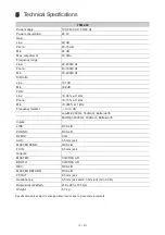
Page 19: ...1 kHz Mic 0 008 at 1 kHz Frequency isolator to 9 dB Low Mid 300 Hz 18db oct Butterworth Mid High 4000 Hz 18db oct Butterworth Inputs LINE RCA L R PHONO RCA L R DJ MIC XLR AUX 3 5 mm jack MASTER SEND RCA L R FX IN 6 3 mm jack Outputs MASTER XLR RCA L R BOOTH XLR RCA L R REC RCA L R MASTER RETURN RCA L R FX OUT 6 3 mm jack Headphones 3 5 mm jack and 6 3 mm jack min 32 Ω Dimensions WxDxH 410 x 285 x ...

Page 20: ... OMNITRONIC 2021 D00137130 Version 1 0 Omnitronic is a brand of Steinigke Showtechnic GmbH Andreas Bauer Str 5 97297 Waldbüttelbrunn Germany ...

Reviews: