14
•
EN
5
Setup
Rack installation
Install the unit on a plane surface or in your rack. For 19" (483 mm) rack installation, 1 unit is required. When
mounting the unit into the rack, please make sure that there is enough space around the device so that the
heated air can be passed on. Steady overheating will damage your device. You can fix the unit with four
screws M6 in the rack.
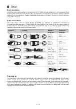
Cable connections
The mixer offers numerous, highly flexible possibilities for balanced or unbalanced connection of
professional audio equipment. To avoid interfering noise, switch off the mixer or set the output controls to
minimum prior to connecting and disconnecting equipment. Be sure to use only high-grade cables. The
illustrations below show the wiring of these cables.
Connector
Structure
Balanced
connection
Unbalanced
connection
XLR, male.
red = 2
black = 3
shield = 1
red = 2
shield = 1 + 3
XLR, female
red = 2
black = 3
shield = 1
red = 2
shield = 1 + 3
6.3mm jack, stereo
red = tip
black = ring
shield = sleeve
red = tip
shield = sleeve +
ring
6.3 mm jack, mono
red = tip
black = ring
shield = n/c
red = tip
shield = sleeve
RCA
red = tip
black = sleeve
shield = n/c
red = tip
shield = sleeve
Powering up
To protect your audio equipment, specifically your speakers, follow this power-up sequence: Set all output
volume controls of any equipment to minimum. Switch on your audio sources first, then the mixer. Always
switch on amplifiers last. Then turn up the volume control on your sources (if provided) and set the output
volume of the mixer to a low level. Turn up the volume controls of your amplifier(s) slowly. Make adjustments
to all volume settings as needed. For switching off, follow the inverse sequence: always switch off amplifiers
first, then the mixer and then the audio sources.
Summary of Contents for EM-312
Page 1: ...1 DE...


