background image


OM9300F Technical Manual 


Rev. 

1.0 

Document No.: 19B00270 

Date: Jan 09, 2018 

Page: 12 

-Ethernet Interface 

PIN 

SIGNAL 

I/O 

Data Out + 

Output Data + 

Data Out - 

Output Data - 

GND 

Ground 

Data IN + 

Input Data + 

Data IN - 

Input Data - 

N.C 


N.C 


N.C 


3.4 Drawer Kick-out Connector (Modular Connector) 
 

The pulse specified by ESC p or DLE DC4 is output to this connector. The 
host can confirm the status of the input signal by using the   

DLE EOT

,

 GS a

, or 

GS r

 commands. 


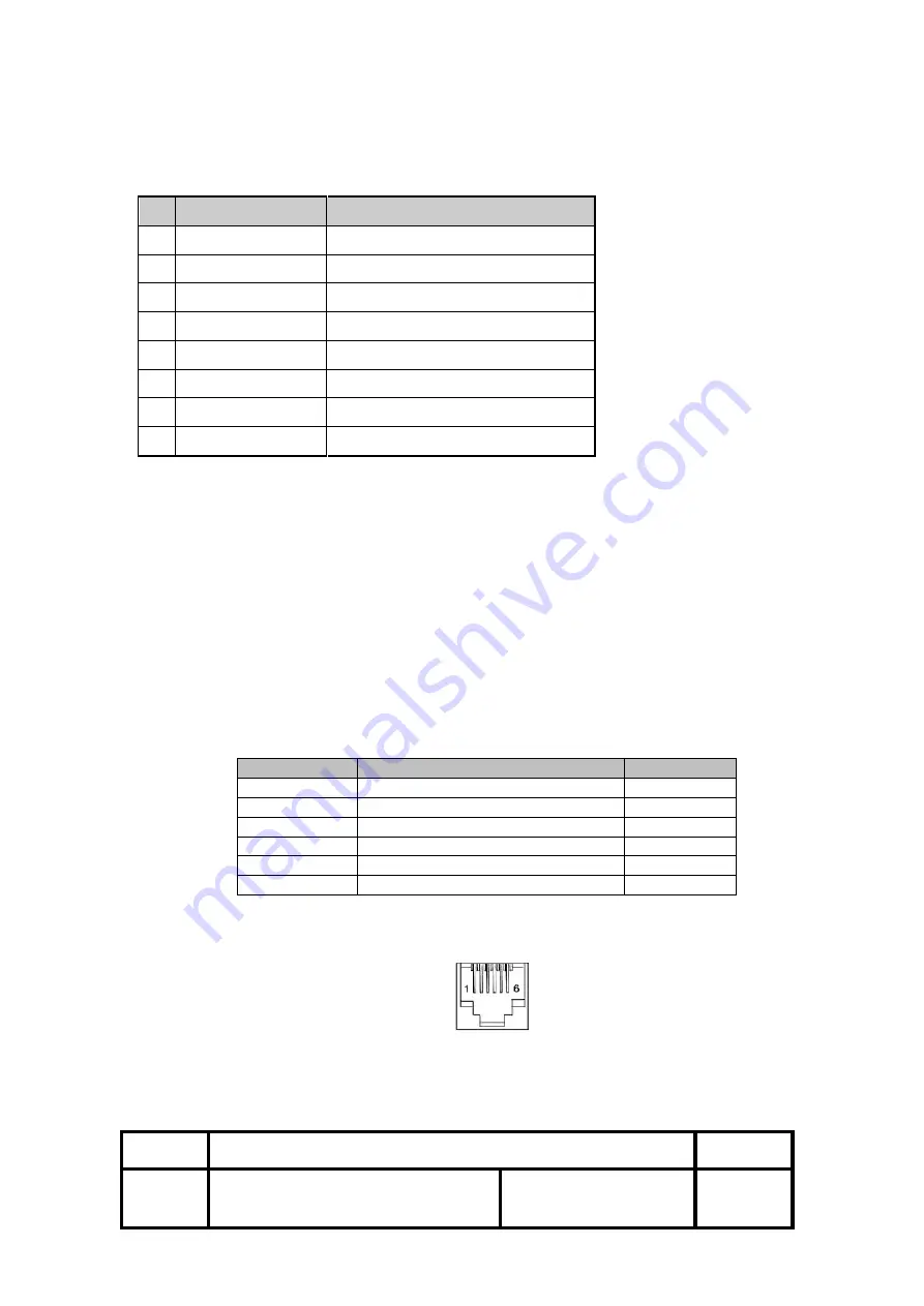
1) Pin assignments: 


Refer to Table 2.2.2 

2) Connector model: 


Printer side: 

RJ11 6P6C, AMP P/N 115837 


User side: 

6-position 6-contact (RJ12telephone jack) 


    < Drawer Kick-out Connector Pin Assignments > 

Pin Number 

Signal Name 

Direction 

Frame GND 

Drawer kick-out drive signal 1 

Output 

Drawer open/close signal 

Input 

+24V 

Drawer kick-out drive signal 2 

Output 

Signal GND 


+24V  is  output  through  pin  4  when  the  power  is  turned  on.  However,  pin  4  must  by 
used only for the drawer. 


< Figure 3.1 Drawer Kick-out Connector > 

    3) Drawer kick-out drive signal 


    Output signal:  Output voltage: Approximately 24V 


    Output current:  1A or less 

Summary of Contents for OM9300

Page 1: ...OM9300 Thermal Receipt printer Technical Manual Revision 1 0 January 9 2018 Omniprint Inc 1923 East Deere Ave Santa Ana California 92705 U S A T 949 833 0080 F 949 833 0040 www omniprintinc com...

Page 2: ...I and Safety Standards Applied Reliability Environmental Conditions 2 Configuration Interface RS 232 serial interface Specifications Switching between on line and off line Interface connector terminal...

Page 3: ...imum approximately 8 inchs sec maximum NOTE Speeds are switched depending on the applied voltage to the printer and head temperature conditions automatically NOTE There may be variations in printing a...

Page 4: ...dot displacement after cutting paper must be fed approximately 1mm 14 360 inches or more before printing 1 4 Paper Roll Supply Device 1 Supply method Drop in paper roll 2 Near end sensor a Detection...

Page 5: ...re 1 1 Paper Roll Printable Area 1 7 Printing and Cutting Positions Manual cutter position Auto cutter blade position Center of the print dot line Figure 1 2 Printing and Cutting Positions NOTE Numeri...

Page 6: ...per thickness in the range 65 to 75 150 million lines based on an average printing rate of 12 5 with paper thickness in the range 76 to 150 2 Cutter Life 10 0 million cuttings if the paper thickness i...

Page 7: ...nter goes off line Between when the power is turned on including reset using the interface and when the printer is ready to receive data During the self test When the cover is open During paper feedin...

Page 8: ...OTES Set the handshaking so that the transmit data can be received Transmit data to the printer after turning on the power and initializing the printer Figure 2 1 Serial transmission bit frame Figure...

Page 9: ...ta received 2 9 DATA0 7 Input Data bit Transmitted 0 7 10 ACK Output Data receiving competed 11 BUSY Output Impossible to printer data receiving 12 PE Output Paper empty 13 SELECT Output Printer s sta...

Page 10: ...STB tHold 2 Busy Peripheral Busy tReady tBUSY nAck tReply tACK tnBUSY tNext 2 1 9 Data Receiving Timing Compatibility Mode Characteristics Symbol Specifications Min ns Max ns Data Hold Time host tHold...

Page 11: ...put Voltage DC 24V 10 2 Current Consumption Operating Approx 1 5 A at ASC printing Peak Approx 10 A at print duty 100 For 10 seconds or less Stand by Approx 0 15 A 3 Power Connector 3 3 USB and Ethern...

Page 12: ...or GS r commands 1 Pin assignments Refer to Table 2 2 2 2 Connector model Printer side RJ11 6P6C AMP P N 115837 User side 6 position 6 contact RJ12telephone jack Drawer Kick out Connector Pin Assignm...

Page 13: ...Waveform 4 Drawer open close signal Input signal level connector pin 3 L 0 to 0 8V H 3 to 5V Figure 3 3 Drawer Circuitry NOTE 1 Use a shielded cable for the drawer connector cable 2 Two driver transis...

Page 14: ...OM9300F Technical Manual Rev 1 0 Document No 19B00270 Date Jan 09 2018 Page 14 4 Printer Appearance...

Page 15: ...e data is not being transmitted to the printer while loading paper 1 To open the paper cover press the latch located on the front left of the Printer as indicated in illustration 4 0 Printer Appearanc...

Page 16: ...OM9300F Technical Manual Rev 1 0 Document No 19B00270 Date Jan 09 2018 Page 16 6 1 5...

Page 17: ...ently turn the printer over and use a small Philips screw driver to remove the cover By changing the switch positions you can modify the default setting for various functions such as cutter mode chara...

Page 18: ...the printer revision number First make sure the printer is turned off and then while pressing the Paper Feed button turn the printer on The printer starts printing its factory setting Code Page Setti...

Page 19: ...ng 18 ESC 3 Set line spacing using minimum units 19 ESC Select peripheral device 20 ESC Cancel user defined characters 21 ESC Initialize printer 22 ESC D Set horizontal tab positions 23 ESC E Select e...

Page 20: ...ion of HRI characters 49 GS I Transmit printer ID 50 GS L Set left margin 51 GS P Set horizontal and vertical motion units 52 GS V Cut paper 53 GS W Set printing area width 54 GS Set relative vertical...

Page 21: ...ould be repeated k times Range The allowable range for the arguments Description Description of the command function Notes If necessary provides important information on setting and using the printer...

Page 22: ...ence to radio or television reception which can be determined by turning the equipment off and on the user is encouraged to try to correct the interference by one or more of the following measures Reo...

Page 23: ...he laws of the member states of the EEC Commission OMNIPRINT INC cannot accept responsibility for any failure to satisfy the protection requirements resulting from a non recommended modification of th...

Reviews: