


CPC 100 V1.41
8 - 4
Pressing the S
E T T I N G S
menu key opens the
Settings
page. The
Settings
page allows setting the test cards individually. As a rule, do not use the
Settings
page but the
Device Setup
tab in the
Options
view (see ”Device Setup” on
page 2-33) to set the test cards. For more information, see ”Settings Page” on
page 2-28.
Defining a Sequence of States
First set the sequence parameters, that is, the parameters that apply to all
states.
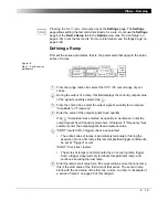
Figure 3:
Step 1 - Set the
sequence parameters
From the range combo box select the
CPC 100
output range of your
choice.
Click the "Sync w/ V1AC" icon to enable or disable this feature.
Enabling "Sync w/ V1AC" synchronizes the
CPC 100
output frequency
with the V1AC input frequency (we recommend a minimum input voltage
of 10V on V1 AC, possible range 48 - 62Hz). In that case, the phase
angle of the output is displayed in the states table rather than the
frequency. Set the phase angle value relative to the phase angle of the
V1 AC input signal (also refer to ”Sync w/ V1AC” on page 3-10).
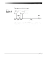
After the start of a sequence the output needs up to 200ms to
synchronize with V1AC. Therefore, define a first state with an amplitude
other than zero.
If disabled, the states table displays the actual frequency value in Hz to
be edited.
"SOOT" (switch off on trigger) check box selected:
• The complete sequence is prematurely terminated if during the
execution of one of its states this state’s specified trigger condition (to
be set at "Trigger") occurs.
"SOOT" check box cleared:
• The sequence is not terminated by an occurring state trigger. Such a
trigger signal will only terminate this particular state, and continue
executing the next state.
1
2
3
4
1
2
3
Summary of Contents for CPC 100
Page 12: ...CPC 100 V1 41 x...
Page 28: ...CPC 100 V1 41 1 16...
Page 90: ...CPC 100 V1 41 3 14...
Page 194: ...CPC 100 V1 41 6 30...
Page 250: ...CPC 100 V1 41 8 32 Figure 24 Settings of Amplifier test card for this example use case...
Page 258: ...CPC 100 V1 41 9 4...
Page 264: ...CPC 100 V1 41 10 6...
Page 282: ...CPC 100 V1 41 12 10 Figure 9 Saving tests with the CPC Editor...
Page 284: ...CPC 100 V1 41 12 12...
Page 312: ...CPC 100 V1 41 14 12...
Page 316: ...CPC 100 V1 41 15 4...
Page 350: ...CPC 100 V1 41 16 34...
Page 372: ...OMICRON Contact Addresses 22...


