background image


ENGLISH


Cod. 710.0151.01.00 Rev0B – 08.2012


6 - 66


3. START UP 

 
3.1 CONTROL PANEL 


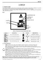
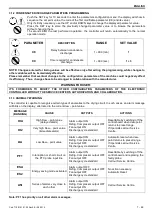
The machines belonging to this series are provided with an electronic system for parameters modification, so eventual 
reset operations can be performed by means of the digital panel located on the front of the dryer. 
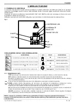
The control panel is composed of 5 keys (ON/OFF, TEST, SET, DOWN e UP) and a 3 digit display, with three signalling 
LEDs indicated by icons (PIC 1). 
 

PIC. 1  

%

DEW POINT

LEVEL

ON/OFF

TEST

COMPRESSOR LED

CONDENSATE

DRAIN LED

FAN MOTOR LED

UP

DOWN

SET


DISPLAY VISUALIZATION AND SIGNALLING LEDS 


DISPLAY 

DESCRIPTION 


the unit is ON with low load 


the unit is ON with normal load 


the unit is ON with normal-high load 


the unit is ON with high load 


LED 

STATUS 

DESCRIPTION


ON  

Compressor energized 

Blinking 

Programming mode activated 


ON 

Condensate drain energized 


ON 

Speed of the fan = 100% 

Blinking 

Speed of the fan < 100% 


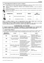
3.1.1 KEYS FUNCTION 


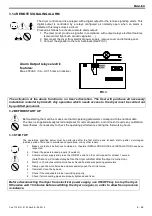
TEST: Pushed for 3 sec. during normal operation, it allows to activate a condensate drainage cycle. 


SET: When pushed and released during normal operation, it displays the set-point value (decimal). 
When  pushed  for  10  seconds,  it  allows  to  enter  the  C8  and  C9  condensate  drain  parameters  programming 
menu (see relevant table). 
When pushed after having set new configuration values, it stores the applied modifications. 


DOWN: When pushed while setting the set point or the configuration parameters, it decreases the displayed 
value of one unit per second, during the first 10 seconds, than of one unit every 0,1 sec. 
When pushed for 10 seconds during normal operation, it starts an automatic test cycle of the controller. 


UP: When pushed while setting the set point or the configuration parameters, it increases the displayed value 
of one unit per second, during the first 10 seconds, than of one unit every 0,1 sec. 


ON / OFF: Pushed for 1 second, it activates or deactivates the process. When the process is deactivated, the 
display shows OFF. The dryer begins to work 2 minutes after the ignition.


NOTE: when the controller is in OFF position, some parts of the dryer are kept under tension therefore, for 
safety purposes, disconnect the electrical power before performing any operation on the machine. 


Summary of Contents for EL 36

Page 1: ...zione GB DIRECT EXPANSION COMPRESSED AIR DRYERS Instruction and Maintenance Manual D DRUCKLUFT K LTETROCKNER Handbuch f r Betrieb und Wartung F SECHEUR D AIR A EXPANSION DIRECTE Manuel d instructions...

Page 2: ......

Page 3: ...e dei tasti 14 3 1 2 Programmazione parametri di scarico condensa 15 3 1 3 Segnalazione anomalie 15 3 1 4 Segnalazione allarme remota 16 3 2 Preliminari di avviamento 16 3 3 Avviamento 16 4 MANUTENZIO...

Page 4: ...teile 66 FR TABLE DES MATIERES 1 INFORMATIONS GENERALES 1 1 Description fonctionnelle 44 1 2 Utilisation du s choir en toute s curit 44 2 INSTALLATION 2 1 R ception et transport 44 2 2 Lieu d installa...

Page 5: ...otice WARRANTY Each product is delivered regularly tested and covered by the warranty conditions specified on the sale list and or on the supply contract SYMBOLS USED IN THE MANUAL AND ON THE DRYER Re...

Page 6: ...irective in force therefore any installation use and maintenance operations must be performed respecting the instructions contained in this manual Any installation use and maintenance operation requir...

Page 7: ...existing we suggest to install a by pass allowing to insulate the machine from the plant thus to facilitate eventual maintenance operations 2 Check the condensate drainage assembly and connect the dra...

Page 8: ...drainage cycle SET When pushed and released during normal operation it displays the set point value decimal When pushed for 10 seconds it allows to enter the C8 and C9 condensate drain parameters pro...

Page 9: ...ITHOUT THE SERVICE CENTER S AUTHORIZATION AND COLLABORATION 3 1 3 ANOMALY WARNING The controller is capable to recognize certain types of anomalies to the drying circuit In such cases an alarm message...

Page 10: ...s supplied already tested and preset for normal operation and it doesn t require any calibration Nevertheless it s necessary to check the operating performances during the first working hours 3 3 STAR...

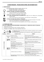
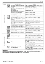
Page 11: ...ol and or maintenance operations must be performed by qualified personnel For maintaining the refrigerating circuit of the machine contact a refrigeration engineer TROUBLE DISPLAY POSSIBLE CAUSE REMED...

Page 12: ...r and call your local distributor Defective fan Replace the fan Protection fuse burned out if present Replace the fuse The temperature control probe is positioned improperly or faulty Check the probe...

Page 13: ...of necessity dismantle the machine and the relevant packaging in compliance with the rules locally in force Pay particular attention to the refrigerant as it contains part of the refrigerating compre...

Page 14: ...e collaudato ed e garantito secondo le condizioni riportate sul listino di vendita e o sul contratto di fornitura SIMBOLOGIE UTILIZZATE NEL MANUALE E SULL ESSICCATORE Leggere il manuale uso manutenzio...

Page 15: ...rmita alle vigenti direttive europee di sicurezza pertanto tutte le operazioni di installazione utilizzo e manutenzione devono essere effettuate secondo le istruzioni contenute nel presente manuale Qu...

Page 16: ...one di un gruppo by pass se non presente che consenta di isolare la macchina dall impianto per agevolare eventuali operazioni di manutenzione Verificare il gruppo di scarico condensa e collegare il tu...

Page 17: ...EST premuto per 3 secondi durante il normale funzionamento consente di attivare un ciclo di scarico condensa SET premuto e rilasciato durante il normale funzionamento visualizza il valore del set poin...

Page 18: ...RO ASSISTENZA 3 1 3 SEGNALAZIONE ANOMALIE Il controllore in grado di riconoscere determinati tipi di anomalie del circuito di essiccazione al verificarsi delle quali visualizza a display un opportuno...

Page 19: ...non richiede pertanto alcuna taratura tuttavia verificarne il corretto funzionamento durante le prime ore di lavoro 3 3 AVVIAMENTO Le operazione sottoriportate vanno eseguite al primo avviamento e com...

Page 20: ...frigorifero della macchina PROBLEMA DISPLAY POSSIBILI CAUSE RIMEDIO PRESENZA DI ACQUA NEL SISTEMA Display del pannello di controllo spento Non c alimentazione nella linea Ripristinare l alimentazione...

Page 21: ...a Controllare la sonda se il problema persiste sostituirla Fuoriuscita di gas dal circuito refrigerante senza carico Spegnere l essiccatore e contattare il proprio distributore La sonda della temperat...

Page 22: ...macchina ed il suo imballo in ottemperanza alle leggi vigenti nel paese di utilizzo Prestare particolare attenzione al refrigerante il quale contiene parti di olio lubrificante del compressore frigor...

Page 23: ...larmente probado y est garantizado seg n las condiciones detalladas en la lista de venta y o en el contrato de suministro SIMBOLOG AS UTILIZADAS EN EL MANUAL Y EN EL SECADOR Lea el manual de uso y man...

Page 24: ...es directivas europeas de seguridad por lo tanto todas las operaciones de instalaci n uso y mantenimiento se deben efectuar seg n las instrucciones contenidas en el presente manual Cualquier operaci n...

Page 25: ...ado que permita aislar la m quina de la instalaci n para facilitar eventuales operaciones de mantenimiento 2 Compruebe el grupo de descarga de condensado y conecte el tubo flexible de descarga a la l...

Page 26: ...del ventilador 100 Parpadeo Velocidad del ventilador 100 3 1 1 FUNCIONAMIENTO DE LAS TECLAS TEST Pulsada por 3 segundos durante el normal funcionamiento activa un ciclo de descarga de condensado SET...

Page 27: ...e anomal as del circuito de secado Cuando se producen anomal as aparece de forma parpadeante el mensaje de alarma correspondiente en una pantalla junto con el valor actual de punto de roc o NOTA PF1 t...

Page 28: ...argo compruebe su correcto funcionamiento durante las primeras horas de trabajo 3 3 ARRANQUE Las operaciones abajo detalladas deben ejecutarse durante el primer arranque y de todos modos cada vez que...

Page 29: ...negativos cuando hay un funcionamiento sin carga Las detecciones de las aver as y eventuales operaciones de verificaci n y o mantenimiento deben ser ejecutadas por personal calificado Contacte a un t...

Page 30: ...istribuidor Ventilador defectuoso Sustituya el ventilador Fusible de protecci n quemado si hay uno presente Sustituya el fusible La sonda de temperatura est colocada incorrectamente Compruebe la sonda...

Page 31: ...m quina y su embalaje con arreglo a las leyes vigentes en el pa s de utilizaci n Preste particular atenci n al refrigerante el cual contiene partes de aceite lubricante del compresor frigor fico En t...

Page 32: ...s Produkt wird vor der Lieferung kontrolliert und nach den auf der Preisliste und oder auf dem Liefervertrag angegebenen Bedingungen berpr ft IM HANDBUCH UND AUF DEM TROCKNER VERWENDETE SYMBOLE Vor de...

Page 33: ...ung der g ltigen europ ischen Sicherheitsvorschriften hergestellt Alle Installations Verwendungs und Wartungsarbeiten m ssen daher nach den im Handbuch angegebenen Anweisungen ausgef hrt werden Alle f...

Page 34: ...lie en Es ist ratsam wenn nicht vorhanden einen By Pass zu installieren die erlaubt die Anlage f r die Durchf hrung von eventuellen Wartungsarbeiten zu isolieren 2 Die Kondensatabscheider berpr fen un...

Page 35: ...sie den Zugang zu dem Parameterprogrammiermen des Kondensatablasses C8 und C9 siehe entsprechende Tabelle Dr ckt man sie nach der Programmierung von neuen Konfigurierungs bzw Setpointwerten so speich...

Page 36: ...LERMELDUNG Die Steuerung kann bestimmte Fehler vom Trocknerzyklus erkennen Es wird in diesen F llen auf dem Display eine St rmeldung abwechselnd mit dem Wert des laufenden Taupunktwertes angezeigt MEL...

Page 37: ...stunden zu kontrollieren 3 3 EINSCHALTEN Die unten beschriebenen Einstellungen und Kontrollen sollen bei erster Inbetriebnahme oder bei erneuter Inbetriebnahme nach langer Stillstandzeit ausgef hrt we...

Page 38: ...ker beauftragen PROBLEM DISPLAY M GLICHE URSACHEN BEHEBUNG VORHANDENSEIN VON WASSER IM SYSTEM Display des Tableus aus Keine Stromversorgung Stellen Sie die Stromversorgung wieder her Probleme mit der...

Page 39: ...enden Sie sich an Ihren H ndler Gebl se defekt Ersetzen Sie das Gebl se Die Sicherung ist durchgebrannt falls vorhanden Ersetzen Sie die Sicherung Der Temperaturf hler wurde falsch positioniert Kontro...

Page 40: ...darf sollen Ger t und entsprechende Verpackung nach den rtlichen Entsorgungsvorschriften entsorgt werden Achtung beim K hlmittel es enth lt Schmier l vom K ltekompressor Bitten wenden Sie sich immer a...

Page 41: ...apr s avoir t test et est garanti conform ment aux conditions figurant dans le tarif et ou le contrat de fourniture SYMBOLES UTILISES DANS LE MANUEL ET SUR LE SECHOIR Lire le manuel d utilisation et d...

Page 42: ...toutes les op rations d installation d utilisation et d entretien doivent tre effectu es conform ment aux consignes donn es dans le pr sent manuel Toute op ration d installation d entretien ou de cont...

Page 43: ...er la machine de l installation pour faciliter d ventuelles op rations d entretien 2 V rifier le groupe de purge des condensants et raccorder le flexible d vacuation la ligne de drainage en se rappela...

Page 44: ...le de purge des condensants SET Si l on appuie dessus pendant le fonctionnement normal elle affiche la valeur du point de consigne Maintenu sous pression pendant 10 secondes elle permet l acc s au men...

Page 45: ...d alarme clignotant sur l cran altern la valeur courante du point de condensation MESSAGE CLIGNOTANT CAUSE SORTIES ACTIONS HtA Point de condensation lev alarme retard e Sortie alarme active Sortie com...

Page 46: ...ur un fonctionnement normal et n a besoin par cons quent d aucun talonnage il convient toutefois de v rifier son bon fonctionnement pendant les premi res heures de travail 3 3 MISE EN MARCHE Les op ra...

Page 47: ...n gative si le s cheur n est pas sollicit A recherche des pannes et les ventuelles interventions de contr le et ou d entretien doivent tre effectu es par du personnel sp cialis Contacter un technicie...

Page 48: ...eur Fusible de protection grill si pr sent Remplacez le fusible La sonde de contr le de temp rature est mal positionn e ou d fectueuse V rifiez la sonde et remplacez la si le probl me persiste Fuite d...

Page 49: ...et son emballage conform ment aux r glementations en vigueur dans le pays d utilisation Faire particuli rement attention au r frig rant car il contient de l huile lubrifiante du compresseur frigorifi...

Page 50: ...Cod 710 0151 01 00 Rev0B 08 2012 48 66...

Page 51: ...Cod 710 0151 01 00 Rev0B 08 2012 49 66 1 1 1 3 C IP 42 1 2 2 2 1 8 50 90 12...

Page 52: ...Cod 710 0151 01 00 Rev0B 08 2012 50 66 2 2 2 3 1 2 3 1 2 3 4 5 6 10 DF 7 5 QF 8 9 10 0 10 3 PF 11 0 01 3 HF 12 0 003 3 CF 13...

Page 53: ...0B 08 2012 51 66 3 3 1 1 5 ON OFF TEST SET DOWN UP 3 DEW POINT LEVEL ON OFF TEST COMPRESSOR LED CONDENSATE DRAIN LED FAN MOTOR LED UP DOWN SET 1 3 1 1 TEST 3 SET 10 DOWN 10 0 1 10 UP 10 0 1 ON OFF 1 O...

Page 54: ...Cod 710 0151 01 00 Rev0B 08 2012 52 66 3 1 2 10 SET 1 UP DOWN SET 15 C8 1 999 1 C9 1 999 1 3 3 1 3 HtA Ht2 LtA PF1 ESA ES2 ASt PF1...

Page 55: ...Cod 710 0151 01 00 Rev0B 08 2012 53 66 3 1 4 1 2 3 3 250 3A AC 15 3 3 2 3 3 1 2 3 4 2 5 6 7 ON OFF 10...

Page 56: ...Cod 710 0151 01 00 Rev0B 08 2012 54 66 4 4 1 1 2 40 200 2000 4 2 ESA 1 ON OFF 2 3 C8 C9...

Page 57: ...Cod 710 0151 01 00 Rev0B 08 2012 55 66 1 C8 C9...

Page 58: ...Cod 710 0151 01 00 Rev0B 08 2012 56 66 4 4 3...

Page 59: ...omatico compr interruptor autom tico del compresor Kompressor Hauptschalter Interrupteur automatique de compresseur 1P2 Fan pressure Switch Pressostato ventilatore Presostato ventilador Druckschalter...

Page 60: ...ES DE FR RU RBF Tap with strainer Rubinetto con filtro V lvula esf rica y filtro depurador Kugelhahn mit Sieb Valve bille avec le tamis PR Air air heat exchanger Prescambio aria aria Pre cambio aire...

Page 61: ...ondensado Entrada de aire Salida de aire DE Kondensatablass Drucklufteintritt Druckluftaustritt FR Purge de condensant Entr e de l air Sortie de l air RU EN Refrigerant line Compressed air line Conden...

Page 62: ...cklufteintritt Druckluftaustritt FR Purge de condensant Entr e de l air Sortie de l air RU EN Refrigerant line Compressed air line Condensate drain line Equalization line IT Linea freon Linea aria Lin...

Page 63: ...B EN WIRING DIAGRAM DE BLOCKSCHALTBILD IT SCHEMA ELETTRICO FR SCHEMA LECTRIQUE ES ESQUEMA ELECTRICO RU EL 36 54 72 108 144 180 216 230V 1Ph 50Hz Cod 714 0104 01 00 Rev 00 EL 36 54 72 108 144 180 216 2...

Page 64: ...Cod 710 0151 01 00 Rev0B 08 2012 62 66 Cod 714 0170 07 00 Rev 00 EL 280 340 230V 1Ph 50Hz...

Page 65: ...FLA Full load current A 1 04 1 30 1 61 3 40 4 10 4 75 3 82 LRA Locked rotor current A 8 50 8 90 11 60 14 00 21 00 24 00 17 00 POW SUPPLY Power supply V Ph Hz 230 1 60 kW Nom consumption KW 0 13 0 24...

Page 66: ...ura ambiente Max Pressione nominale Pressione max Punto di rugiada Refrigerante Peso ES Temp Ambiente max Press nominal Press Max Punto de roc o Refrigerante Peso DE Max Raumtemperatur Betriebsdruck M...

Page 67: ...4 390 432 441 100 85 65 45 65 12 1 2 BSP NPT 1 2 BSP NPT 6mm 230 1 50 60 V ph Hz EL 72 390 432 441 100 85 65 45 65 12 EL 108 390 432 441 100 85 65 45 65 12 EL 144 420 516 551 100 85 80 44 63 12 3 4 BS...

Page 68: ...10 1949 00 SC Heat exchanger base 904 0097 01 904 0101 01 904 0101 01 904 0101 01 904 0102 01 904 0103 01 904 0103 01 904 0156 01 904 0156 01 FR Net filter 630 0041 00 630 0041 00 630 0041 00 630 0041...

Page 69: ......
Reviews: