background image

7 | 

P a g e


Hardware Setup 

Connecting your Antenna 

The XW Transmitter comes with a 2.4 GHz Antenna. 


Step 1: 

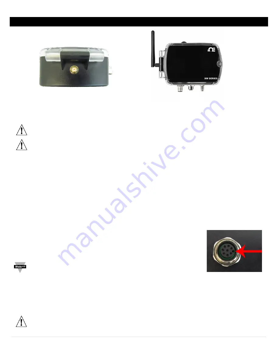
Line up the supplied 2.4 GHz antenna with the receiving connector on the XW Transmitter. See 

Figure 2

.


Step 2: 

Turn the plastic knurl on the antenna in a clockwise direction. See 

Figure 3

 for result. 

Important: 

Hand tighten the antenna onto the XW Transmitter.


Important: 

Before powering up the XW Transmitter ensure the supplied antenna is properly installed. Running the 

XW Transmitter without an antenna, or with an unapproved antenna, may cause damage to the device and/or 

cause operation outside of regulatory compliance. Omega Engineering accepts no liability and issues no warranty 

for devices operated improperly. 


Connecting your Sensors 

The XW Transmitter works with a wide variety of sensors. Most sensors come packaged in a probe and each probe is suited 

to different applications. Some probes may contain multiple sensors. The XW Transmitter automatically detects connected 

sensors on power up and transmits that data to the SYNC configuration software. 


For a complete list of sensors compatible with the XW Transmitter, please visit the Omega website. 


Probe Installation 

8-pin digital probes, including Omega Smart Probes, can be plugged in at this point. Digital I/O or Analog connections should 

be made after the XW Transmitter is setup. To install or change a probe, follow these directions: 


Step 1: 

Ensure the XW Transmitter is powered OFF. 


Step 2:

 Take note of the Key Position on the XW Transmitter. See 

Figure 4

. Align this key 

with the keyway in the mating connector on the XW Transmitter. 

Note: 

The keyway locations in this manual assume the device is standing in the 

position displayed in 

Figure 4


Step 3: 

Turn the metal knurl of the probe in a clockwise direction while leaving the probe body stationary. Ensure that the 

probe or interconnecting cable is inserted to the base of the knurl to maintain a NEMA 4 rating on the XW Transmitter. 


Step 4: 

To remove the probe, grasp the plastic knurl only and turn it in a counter clockwise direction. Do NOT rotate the 

probe body. 

Caution: 

Do not rotate the body of the probe or the cable. Do not use pliers, vice grips or other tools on probes. 

Hand-tighten and hand-loosen only. 


Figure 2 

Figure 3 

Figure 4


Summary of Contents for XW-ED

Page 1: ...1 P a g e TM User sGuide Shop online at omega com e mail info omega com For latest product manuals www omegamanual info XW ED XW EDA PRO XW EDA XW EDA PRO Long Range Wireless Transmitter...

Page 2: ...nly Customer Service 1 800 622 2378 USA Canada only Engineering Service 1 800 872 9436 USA Canada only U S A Headquarters Tel 203 359 1660 e mail info omega com Fax 203 359 7700 The information contai...

Page 3: ...teries 8 Coin Cell Battery and Replacement 9 AC Adapter 9 Power Button 10 Configuring your ZW REC 10 Connecting your XW Transmitter 10 Connecting to SYNC Auto Detect 11 Connecting to SYNC Manual 12 Co...

Page 4: ...asurements 24 Counter Measurements 25 Appendix B Specifications 26 Wireless Communication 26 Power 26 Environmental 26 Packaging 26 General 26 XW ED and XW ED PRO Inputs 27 Digital Inputs 27 Process I...

Page 5: ...ying documents Tip Provides helpful hints Safety and EMC Considerations ESD Warning Warning The following parts of the unit are ESD Electro Static Discharge sensitive Antenna Metal Connectors for sign...

Page 6: ...ain data even when your power goes out programmable logic for triggering I O easy configuration through SYNC configuration software and event logging Included with Your XW Transmitter 2 4 GHz Antenna...

Page 7: ...to the SYNC configuration software For a complete list of sensors compatible with the XW Transmitter please visit the Omega website Probe Installation 8 pin digital probes including Omega Smart Probe...

Page 8: ...ies To install the batteries follow these steps Step 1 Unscrew the lid of the transmitter using a Philips head screwdriver and open the device Note The battery orientation is marked on the battery hol...

Page 9: ...sert the new Coin Cell battery Important The positive battery terminal contact the large terminal and faces the top of the XW Transmitter AC Adapter The XW Transmitter may also be powered using line p...

Page 10: ...ning SYNC SYNC will pull the IP Address Network Mask Gateway and Network ID from your ZW REC Step 1 Turn on your PC and ensure that SYNC is downloaded installed and running Step 2 Plug in your ZW REC...

Page 11: ...le ZW RECs you will have to choose which ZW REC you would like to connect to by selecting the Network ID of your preferred ZW REC Step 3 Assign a unique Device ID to your XW Transmitter Note The Devic...

Page 12: ...blished Command Timeout The maximum time in milliseconds for a command to be completed before the command is aborted The default command timeout is 500 milliseconds It is recommended that this section...

Page 13: ...with the clock of the computer it is connected to Important Click Update Current Time when setting up the XW Transmitter for the first time to ensure accurate date and time are reflected in the data...

Page 14: ...rams of the XW Transmitters proceed through this manual to find the relevant connection type XW ED Wiring The XW ED is a versatile transmitter that can accept a wide variety of digital probes function...

Page 15: ...gnal DELAY Delay Timer Measure the time Between the Rising or Falling Edges of 2 Signals CNT Up Counter Totalizer Counter with Enable and Reset U D_CNT Up Down Counter Totalizer Counter with Direction...

Page 16: ...ested P 2 3 4 P 7 P 8 3 3V Pull Down Pulse TTL Input Do not Exceed 3 3V at Input Pin For Active High Select Normally Open For Active Low Select Normally Closed Figure 25 NPN or N MOS Transistor Input...

Page 17: ...ption in the side bar Note When using Dual Process the Device Range Type section is only available for Input 0 Input 1 is always the same type as Input 0 Warning Be sure to setup the unit before plugg...

Page 18: ...Single TC or Dual TC using SYNC Cold Junction Compensation The thermocouple input interface offers cold junction compensation calibration To achieve proper Ice Point calibration you must be able to im...

Page 19: ...0 Input 1 is always the same type as Input 0 Warning Be sure to setup the unit before plugging in Process inputs RTD Input The RTD Input interface provides interfaces to type 100 500 and 1000 ohm 385...

Page 20: ...required 3 Wire RTD Connections This connection is best suited for devices like strain gauges and is most often seen in industrial process and monitoring applications 4 Wire RTD Connections A 4 Wire...

Page 21: ...al I O Pro Discrete Input Output Connector Input Settings To use a pin as an input make sure it is set to Active Low default in the Output Tab in SYNC The Input can then be set as Active High or Low i...

Page 22: ...ance state HIGH When the output is active it is in a high impedance state Value OFF Set output inactive ON Set output active PWM Pulse Width Modulation controls the amount of power given to a device b...

Page 23: ...e Output configuration tab in SYNC and click on the icon located to the right of the available outputs Clicking the icon will open the Define ON OFF Control dialog box as seen in Figure 36 Choose the...

Page 24: ...positive or negative pulse edge depending on the signal type and modifier chosen RST Resets the value to 0 when active ENB Enables measurement when active Holds the last measurement when inactive CLK...

Page 25: ...n CLK_A Measures the positive or negative pulse depending on the signal type and modifier chosen RST Resets the counter to 0 depending on the signal type and modifier chosen ENB Sensor starts measurin...

Page 26: ...hium Back Up Battery CR2032 included RTC back up only Safety Qualified AC Power Adaptor optional Nominal Output 5 VDC 0 6 A Input 100 to 240 VDC 50 60 Hz Operating Temperature 0 to 40 C 32 to 104 F En...

Page 27: ...200 C 0 4 C K 160 C to 1372 C 0 4 C T 190 C to 400 C 0 4 C E 220 C to 1000 C 0 4 C N 100 C to 1300 C 0 4 C R 40 C to 1788 C 0 5 C S 100 C to 1768 C 0 5 C B 640 C to 1820 C 0 5 C C 0 C to 2320 C 0 4 C...

Page 28: ...ext Symptom Blue Light blinks on and off rapidly XW ED does not show up on the ZW REC webpage Solution Use Omega Sync to check that NID is the same as the ZW REC and that the DID is not used by anothe...

Page 29: ...d drywall anchors if needed Step 4 Use the included screws to secure the XW Transmitter Tip When mounting the unit be sure to leave room on the top to access the power button and on the bottom and sid...

Page 30: ...ment The CE declaration is available at the website listed on the cover page of this manual FCC IC Part 15C Class DTS Intentional radiator Contains TX FCC ID TYOJN5168M5 Contains Industry Canada ID IC...

Page 31: ...A if the unit is found to be defective it will be repaired or replaced at no charge OMEGA s WARRANTY does not apply to defects resulting from any action of the purchaser including but not limited to m...

Page 32: ...s M U Turbine Paddlewheel Systems M U Totalizers Batch Controllers pH CONDUCTIVITY M U pH Electrodes Testers Accessories M U Benchtop Laboratory Meters M U Controllers Calibrators Simulators Pumps M U...

Reviews: