


2
3
4
START HERE
Layer N SS-002 Overview
Important:
The battery polarity is marked
inside the compartment. Promptly remove
dead batteries to prevent loss of data and
potential damage due to leaking batteries.
External Sensor
Pin 1
Pin 2
Pin 3
Thermocouple
TC1 +
TC1 -
Not Used
RTD
2-Wire
Color 1
Color 2
Short Pin 1
& Pin 3
3-Wire
Color 1
Color 2
Color 1
4-Wire
Color 1
Color 2
Color 1
Dry Contact
Switch
Not Used
Common
Note:
For RTD connections, Pin 3 is the
excitation constant current source.
For 2-Wire RTD connections, a short copper
wire is needed form Pin 1 to Pin 3.
For 4-Wire RTD connection, only connect one
“Color 2” wire at Pin 2. The second “Color 2”
wire needs to be cut.
Introduction
Use this Quick Start Guide to set up your Layer N
SS-002 TC and RTD Smart Sensor.
Materials
Included with your SS-002
• Layer N SS-002 unit
• Quick start guide
• 2x AA alkaline batteries
• Sub GHz Antenna
• Terminal block connector
Additional Materials Needed
• A Windows 7,8, 9, 10, or 11 OS PC or laptop with
Omega’s free SYNC configuration software
• A compatible Layer N Gateway
• A Layer N Cloud account or a qualifying Omega
Enterprise Gateway license tier (Pro, Business, or
Business Pro)
Optional Materials
• External TC, RD, or Contact Closure
• Micro USB 2.0 (for SYNC configuration)
• SYNC Configuration software
-Downloadable on the OMEGA website
Important:
Do not power on the Layer N
Gateway or Smart Sensor before Gateway
registration is complete.
SS-002 Hardware Setup
Step 1: Install the antenna to the side of the
connector on the SS-002 unit.
Step 2: Insert the 2x AA batteries into the battery
compartment located on the underside of
the SS-002 unit.
Before you Begin
Before you begin setting up your SS-002, ensure
you have created a Layer N Cloud or Omega
Enterprise Gateway account and registered the
Layer N Gateway that will be paired with the SS-002
device.
During the gateway setup process, the gateway will
automatically download the latest firmware and
re-boot. Once the gateway is registered and the
pairing button LED is green you may continue with
the SS-002 installation.
The
Pairing Button of the Smart Sensor will power up
to a solid orange LED light in the center of the pairing
button indicating that the device has been successfully
powered on. Refer to the LED Status indicator table
below:
LED Color
Status
Amber/Orange
(solid)
SS-002 is powered on; not connected
to a Gateway
Green (blinking
repeatedly)
SS-002 is in Pairing Mode
Amber/Orange
(blinking
repeatedly)
SS-002 is reconnecting to a paired
Gateway
Green (flash
periodically)
SS-002 is communicating to a Gateway
Green (solid)
SS-002 is performing a radio firmware
update
Red (solid)
The reset button has been held for a
radio factory reset
Red and Green
(blinking)
A password error has occurred
No Light
The SS-002 is asleep or the battery is
drained
Pairing to your Layer N Gateway
Once the
Pairing Button displays a solid orange LED light
in the center of the pairing button, your Smart Sensor is
ready to be connected to a Layer N Gateway. Pairing your
SS-002 with a Layer N Gateway is made easy with a one-
button pairing system between the two devices.
Step 1: Push the pairing button once on your
SS-002 unit. The LED status indicator will blink
green indicating the device is in Pairing Mode.
When the Smart Sensor has been successfully paired to
your Layer N Gateway, the green LEDs on both devices
will stop flashing within 2 minutes.
The Smart Sensor LED will periodically flash green each
time data is transmitted to the gateway.
As measurements are transmitted, you will begin to see
data appearing on the Layer N Cloud or OEG interface.
The transmission interval can be adjusted from the Layer
N Cloud Interface or from the OEG interface, depending
on which platform the Gateway is connected to.
Step 2: Quickly push the pairing button on the Layer
N Gateway. The LED on the gateway will blink
green indicating the gateway is in Pairing Mode.
Once your SS-002 has successfully paired to your
registered Layer N Gateway, the SS-002 will appear
on the Layer N Cloud interface or the OEG interface
and begin transmitting data.
View Readings on Layer N Cloud or OEG
For additional information on the customizable
features made available through the micro USB
connector, continue to the sections titled
Advanced
Configuration with SYNC and Smart Sensor USB
Connector.
Sensor Mix Configuration
To configure the sensor mix in your SS-002,
connect a micro USB 2.0 cable from your Smart
Sensor device to your PC or laptop running SYNC
configuration software.
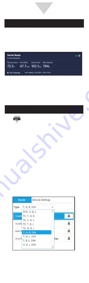
Step 1: Once your device has been auto-detected
by SYNC, click the
Type dropdown in the
Inputs interface.
Advanced Configuration with SYNC
The SS-002 can be configured using SYNC
configuration software by connecting through the
micro USB 2.0 port. SYNC can be used to configure
alarms in the sensor, set device passwords, and
update firmware.
Note:
SYNC configuration software is
downloadable on the OMEGA website.
The
SS-002-0 offers a configurable choice of one
external thermocouple, RTD, or DIN (contact
closure).