


RD100B
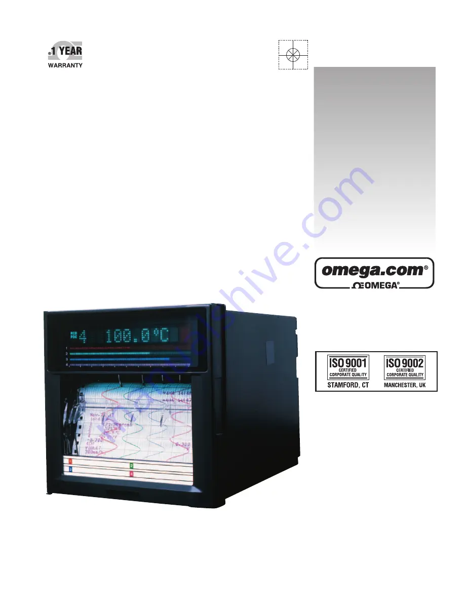
Programmable Recorder
omega.com
e-mail: [email protected]
For latest product manuals:
omegamanual.info
Shop online at
User’s Guide
Summary of Contents for RD100B
Page 232: ...Index 4...
Get all the information you need on the Omega RD100B with our free User Manual download. The manual provides detailed instructions on how to use your device efficiently. Download it for free from our manualshive.com to enhance your user experience and make the most out of your product.
RD100B
Programmable Recorder
omega.com
e-mail: [email protected]
For latest product manuals:
omegamanual.info
Shop online at
User’s Guide
Page 232: ...Index 4...


