Step Four
PREPARATION
A. Supply Voltage:
The transmitter power supply voltage should
never exceed a maximum of 28 VDC. Omega controllers and meters
have built-in 24 VDC power supplies for use with the transmitter.
Alternative controllers and/or power supplies with a minimum output
of 12 VDC may also be used with the transmitter for calibration
and/or operation.
B. Cable Length:
The cable length between the transmitter and
it’s point of termination may be extended up to a maximum of 1000
feet, using a well-insulated, shielded wire from 14 to 18 gauge.
C. Factory Span:
All transmit-
ter models are factory calibrated with
4 mA at their maximum range (tank
empty) and 20 mA at their minimum
range (tank full). The 4 and 20 mA
span set points can be reverse cali-
brated on all models.
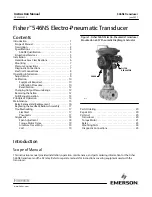
D. Maximum Applied Range:
The Individual or cumulative effects
of agitation, vapor or foam can
reduce the overall quality of signal
return and shorten the maximum
applied range of the transmitter. To determine the maximum applied
range of the transmitter in your application, refer to the below derat-
ing chart.
20 mA
4 mA
50Khz
0
1
2
3
4
5
6
7
8
9
10
0%
50%
100%
Maximum Applied Range Derating Chart
LVU800
Agitation = 1-3 @ 50 kHz
Vapor
= 3-5 @ 50 kHz
Foam
= 4-6 @ 50 kHz
Step Five
MENU ITEMS
A. WARMUP:
This is the initial power up mode. When this mes-
sage is displayed, the transmitter is going through its power up rou-
tine, and validating the target value. After a short period of time, this
message will disappear and be replaced by a numeric value.
B. FULL:
Level has reached the programmed FULL set point.
C. EMPTY:
Level has reached the programmed EMPTY set point
D. UNITS:
Selectable in Inches Centimeters or Percent. The facto-
ry default is Inches.
E. INCHES:
Inch units of measurement.
F. CM:
Centimeters units of measurement.
G. PERCNT:
0-100% units of measurement. Percent is the calcu-
lated value based on the 4mA and 20mA set points.
H. DISPLAY:
Allows the user to select if the display will read in
units of air or units of liquid. Factory default is units of air.
H. TANK:
Menu through which the 4-20 mA span is adjusted.
I. HEIGHT:
The point in inches
or centimeters from the transducer
face where the output will be 4 mA
(generally the bottom of the tank).
Factory default is the same as the
unit’s maximum range. Example:
LVU816 = 197” maximum range
which is also the same 4 mA set
point under factory default.
J. Fill H (Fill Height):
The
point in inches or centimeters from
the bottom of the tank to the high
level where the output will be 20
mA (generally the straight wall dis-
tance from the bottom of the tank).
NOTE: The transmitter dead band
is automatically subtracted from
the FILL H. Example: LVU816 =
8” dead band. Therefore the maxi-
mum FILL H is 197” [maximum
range] - 8” [dead band] = 189”.
K. REV mA (Reverse mA):
Allows the user to select 20 mA at
the bottom and 4 mA at the top of the tank (20-4 mA). Factory default
is 4 mA (MaxR) at the bottom and 20 mA (MinR) at the top.
L. SAFE:
The FAIL-SAFE current output of the transmitter if the
acoustic signal is LOST. Selectable at 4 mA, 20 mA, 21 mA, 22 mA
or HOLD. (HOLD is the last 4-20 mA value prior to LOST).
M. TG CAL:
Allows the user to use an unknown distance for setting
of the 4 mA and 20 mA span.
HEIGHT
(MaxR)
FILL H
(MinR)
EMPTY
FULL
LVU800 Series
Reverse Mode