


6
SENSOR
INFORMATION
(tuning
fork)
Step
Three
Tuning
Fork
Switch
(LTU
‐
101A
Series):
The
Tuning
Fork
switch
operates
at
a
nominal
frequency
of
400
Hz.
As
the
switch
becomes
immersed
in
a
liquid
or
slurry,
a
corresponding
frequency
shift
occurs.
When
the
measured
frequency
shift
reaches
the
set
point
value,
the
switch
changes
state
indicating
the
presence
of
a
liquid
or
slurry
medium.
For
optimum
performance
and
proactive
maintenance,
the
sensor
automatically
adjusts
for
coating,
and
if
necessary,
outputs
a
preventative
maintenance
alarm.
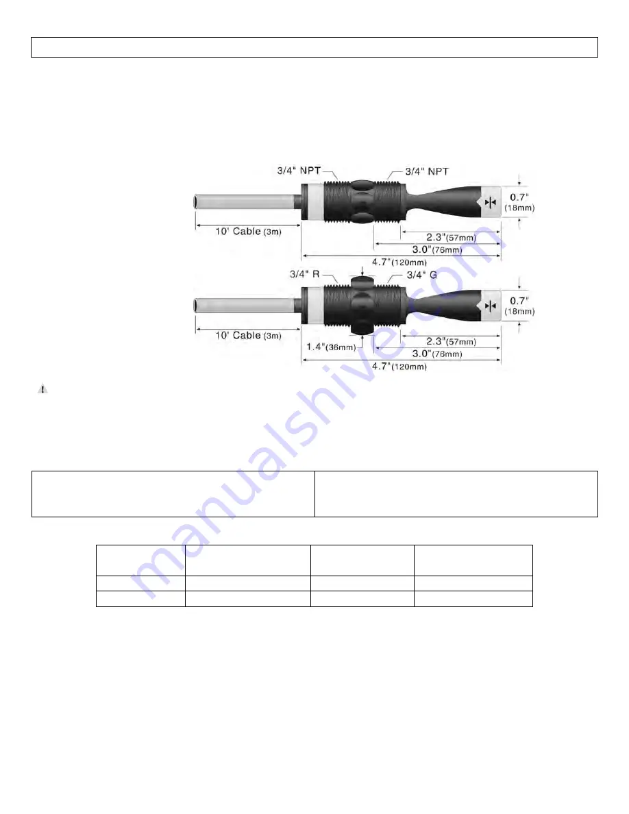
LTU
‐
101A
‐
R
LTU
‐
101A
‐
G
‐
R
Do
not
squeeze
the
forks
together.
Doing
so
could
damage
or
break
the
sensor
and
void
the
warranty.
When
powering
up
the
LTU
‐
101A
series,
the
start
‐
up
procedure
requires
the
switch
to
cycle
through
a
wet
condition
for
1/2
second
in
order
to
determine
an
initial
resonance.
LTU
‐
101A
Series
Specifications:
Sensor
material:
PPS
(glass
fill)
FKM
cable
grommet
Maint.
alarm:
NPN
transistor,
10
mA
max.
Cable
jacket
mat’l:
PP
Cable
type:
5
‐
conductor,
#24
AWG
(shielded)
Configurations:
Part
Number
Material
(body)
Material
(cable)
Thread
(inside
x
outside)
LTU
‐
101A
‐
R
Polyphenylene
Sulfide
Polypropylene
¾”
NPT
x
¾”
NPT
LTU
‐
101A
‐
G
‐
R
Polyphenylene
Sulfide
Polypropylene
¾”
R
x
¾”G
Note:
all
tuning
fork
level
switches
are
available
with
longer
lengths
cable
of
25’
and
50’.
For
25’
of
cable,
add
(
‐
25)
to
the
end
of
the
part
number
and
for
50’
of
cable,
add
(
‐
50)
to
the
end
of
the
part
number.
Example,
LTU
‐
101A
‐
R
‐
25
will
have
25’
of
cable.