


INTRODUCTION
TECHNOLOGY
Step Three
A. Application:
The general purpose ultrasonic level switch pro-
vides non-contact level detection up to 26’ or 8m with 3 relays. Each
relay can be configured on a single set point alarm, two latched set
points for automatic fill or empty, two set points for out of bounds
alarms or three set point (relays 1 and 2 only) alternation / duplexing
. The switch is well suited for a wide range of corrosive, waste and
slurry type media, and is broadly selected for atmospheric day tank,
pump lift station and waste sump applications.
B. Part Number:
The part and serial numbers are located on the
wrench flat. Check the part number on the product label and confirm
which of the below model configurations you have purchased:
Part Number
Range
Supply
Mount
LVCN704
4’ (1.2m)
95-250 VAC
1” NPT
LVCN704G
4’ (1.2m)
95-250 VAC
1” NPT
LVCN704-DC
4’ (1.2m)
12-28 VDC
1” NPT
LVCN704G-DC 4’ (1.2m)
12-28 VDC
1” NPT
LVCN709
9.8’ (3m)
95-250 VAC
1” NPT
LVCN709G
9.8’ (3m)
95-250 VAC
1” NPT
LVCN709-DC
9.8’ (3m)
12-28 VDC
1” NPT
LVCN709G-DC
9.8’ (3m)
12-28 VDC
1” NPT
LVCN716
16.4’ (5m)
95-250 VAC
1” NPT
LVCN716G
16.4’ (5m)
95-250 VAC
1” NPT
LVCN716-DC
16.4’ (5m)
12-28 VDC
1” NPT
LVCN716G-DC
16.4’ (5m)
12-28 VDC
1” NPT
LVCN726
26.2’ (8m)
95-250 VAC
2” NPT
LVCN726G
26.2’ (8m)
95-250 VAC
2” NPT
LVCN726-DC
26.2’ (8m)
12-28 VDC
2” NPT
LVCN726G-DC
26.2’ (8m)
12-28 VDC
2” NPT
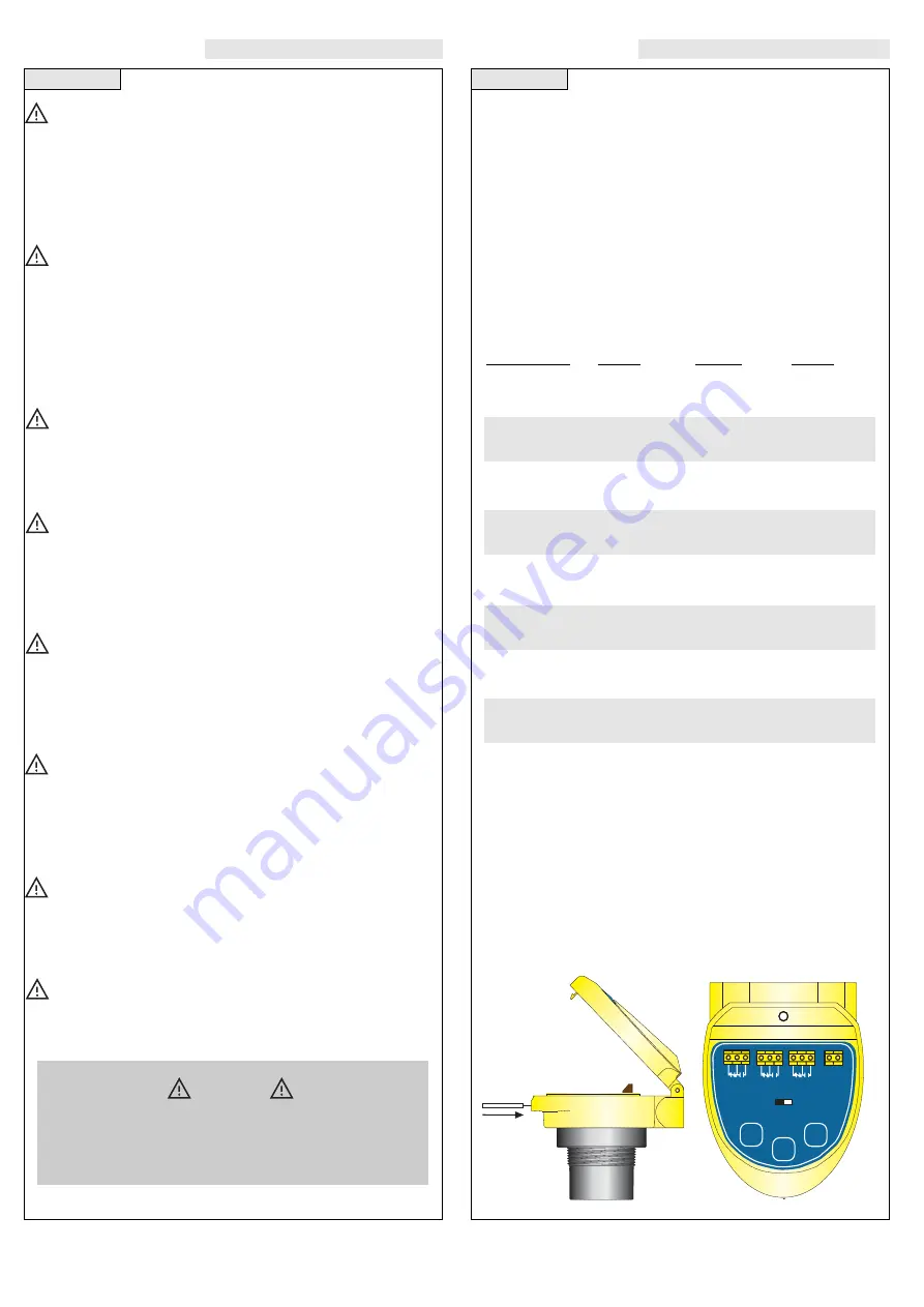
C. NEMA 4X Enclosure:
The enclosure has a flip cover with two
1/2” NPT female conduit ports and an internal terminal strip for
wiring. To open the enclosure, you will need a small insertion tool
such as a screwdriver. Insert the tool into the hole located at the
front of the enclosure and gently push on the latching mechanism
to release the cover. Rotate the hinged cover up for 135° access to
the faceplate and terminal strips. Before closing the enclosure,
make sure that the enclosure gasket is properly seated, and
that any conduit fittings, cable connectors or plugs are
installed correctly and sealed.
Step Two
About this Manual:
PLEASE READ THE ENTIRE MANU-
AL PRIOR TO INSTALLING OR USING THIS PRODUCT. This
manual includes information on the LVCN700 series
Ultrasonic Level Switch. Please refer to the part number
located on the switch label to verify the exact model con-
figuration which you have purchased.
User’s Responsibility for Safety:
Omega manufactures a
broad range of level sensing technologies. While each of these sen-
sors is designed to operate in a wide variety of applications, it is the
user’s responsibility to select a sensor model that is appropriate for
the application, install it properly, perform tests of the installed sys-
tem, and maintain all components. The failure to do so could result
in property damage or serious injury.
Proper Installation and Handling:
Only properly trained
staff should install and/or repair this product. Install the switch with
the included Viton gasket and never overtighten the switch within
the fitting. Always check for leaks prior to system start-up.
Wiring and Electrical:
A supply voltage of 95-250 VAC is
used to power the Ultrasonic switch, and a supply voltage of 12-28
VDC is used to power the optional DC version of the LVCN700
series Ultrasonic switch. Electrical wiring of the switch should be
performed in accordance with all applicable national, state, and
local codes.
Material Compatibility:
The LVCN700 series enclosure is
made of a flame retardant Polycarbonate (PC/ABS FR). The trans-
ducer is made of Polyvinylidene Fluoride (PVDF). Make sure that
the model which you have selected is chemically compatible with
the application media.
Enclosure:
While the LVCN700 series housing is liquid-resis-
tant, the unit is not designed to be operational when immersed. It
should be mounted in such a way that the enclosure and transduc-
er do not come into contact with the application media under nor-
mal operational conditions.
Make a Fail-Safe System:
Design a fail-safe system that
accommodates the possibility of switch and/or power failure.
OMEGA recommends the use of redundant backup systems and
alarms in addition to the primary system.
Flammable, Explosive or Hazardous Applications:
The LVCN700 series should not be used within classified haz-
Warning
Always use the Viton gasket when installing the Ultrasonic
switch, and make sure that all electrical wiring of the switch
is in accordance with applicable codes.
LVCN726
Shown
RELAY
1
RELAY
2
RELAY
3
L
1
L
2
POWER
Cal. Run
High
Low
Select
All manuals and user guides at all-guides.com


