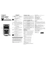
background image

HH911T, HH912T

Thermocouple Thermometer

TM

  e-mail: [email protected] 

For latest product manuals: 

www.omegamanual.info

Shop online at 

omega.com

User’s Guide

Summary of Contents for HH911T

Page 1: ...HH911T HH912T Thermocouple Thermometer TM e mail info omega com For latest product manuals www omegamanual info Shop online at omega com User sGuide ...

Page 2: ...erves the right to alter specifications without notice Servicing North America U S A Omega Engineering Inc Headquarters Toll Free 1 800 826 6342 USA Canada only Customer Service 1 800 622 2378 USA Canada only Engineering Service 1 800 872 9436 USA Canada only Tel 203 359 1660 Fax 203 359 7700 e mail info omega com For Other Locations Visit omega com worldwide ...

Page 3: ...enu 3 3 View Modes and Statistics 3 4 Auto Power Off 3 5 Backlight and Backlight Timeout 3 6 Hold Function 3 6 Trend Indicators 3 6 Battery Indicator 3 6 Probe Offset 3 7 Open Wire Detection On Off 3 8 Clear Function 3 9 Invalid Measurement Indications 3 9 Resolution and Rounding Functions Serial Number 2148 and later 3 9 4 Service Information 4 11 Inspection and Cleaning 4 11 Calibration 4 11 4 2...

Page 4: ...tors Display Backlight Four 4 LED Backlight with 30 second timeout Display Resolution 0 1 1000 1 1000 Reading Rate 3 Second for Readings and Trend Indicators Battery Type 3 AA IEC LR6 ANSI 15 Alkaline Battery Life 2000 Hours Typical Battery Indicator Four 4 Stage Battery Charge Indicator Statistics Minimum Reading Maximum Reading Average Reading Reading Range Standard Deviation T1 T2 HH912T only K...

Page 5: ...5 RH 30 to 40 C 86 to 104 F 5 to 85 RH 40 to 55 C 104 to 131 F 5 to 60 RH Altitude 0 to 4600 m 0 to 15 092 ft Vibration Random 10 500 Hz 0 03 g2 Hz Shock 30g Half Sine Drop 4 Drops from 1 m to Concrete Storage Temp 40 to 71 C 40 to 159 F PHYSICAL CHARACTERISTICS Dimensions 193 x 84 x 28 mm 7 6 x 3 3 x 1 1 in Weight incl Batteries HH911T 300 9 g 10 6 oz HH912T 303 2 g 10 7 oz 1 For complete instrum...

Page 6: ...Instrument Description 2 3 Data Thermometers HH932T Data Thermometer Dual Input ...

Page 7: ...th LED Backlight Four 4 NIST traceable thermocouple types J K T and E Comprehensive real time statistics MIN MAX AVG RNG STDEV and T1 T22 Easy to clean Probe offset function to minimize probe error 0 1 1 display resolution F C and K temperature units Reading HOLD mode Conforms to ITS 90 thermocouple tables Durable Meets MIL PRF 28800F Class 2 requirements Tilt Stand Magnet Hanger User friendly ope...

Page 8: ...rical potential the user is responsible for obtaining and properly using a probe that provides adequate insulation between the surface with elevated potential and the thermocouple wiring Always disconnect probe leads before opening the battery door or the instrument housing Internal circuits can present a shock hazard if leads are connected to a source of elevated potential Do not use this instrum...

Page 9: ... mix old and new batteries Do not apply voltages across thermocouple leads in excess of normal thermocouple voltage for the selected range Excessive input voltage could result in blown fuse component damage or fire Application of excessive voltage is not covered by the warranty Avoid making sharp bends in probe or sensor lead wires Bending lead wires at sharp angles can damage the wire and cause p...

Page 10: ...instrument off and disconnect any input connections before replacing the batteries Re install the battery compartment cover before resuming use of the instrument CAUTION The battery compartment is sealed with a rubber gasket Use care to not damage the gasket when removing or installing the battery compartment cover CAUTION Remove the batteries when storing the instrument for an extended period of ...

Page 11: ...located at the top of the instrument To ensure best measurement accuracy allow several minutes for the thermocouple probe and connector to thermally stabilize after connection to the instrument 3 The instrument will immediately display a temperature measurement for the connected channels However to ensure valid and best accuracy measurements continue to Step 4 below 4 Set the desired measurement p...

Page 12: ...et for more information g Momentarily press to save your selection and move to Channel 2 probe offset if equipped h If desired repeat Step f above for Channel 2 i Momentarily press to save your selection and exit the setup menu Congratulations You re now ready to make accurate and reliable temperature measurements wherever and whenever you may need to We know you are eager to begin using your new ...

Page 13: ...in Setup Menu save current value and step to next parameter Toggle display backlight 1 5s Disable backlight 30 second timeout Hold currently displayed measurement 1 5s Reset all statistics currently stored in memory While in Setup Menu discard all unsaved changes and exit menu Cycle through view modes and statistics While in Setup Menu save changes and exit menu While in Setup Menu advance or reve...

Page 14: ...rement 4 The active thermocouple type 5 Remaining battery life 6 Active temperature unit 7 Channel 2 temperature measurement2 T1 T2 measurement result2 or active statistic result 8 Active statistic 9 Open Wire Detection Off 10 Setup Menu active 11 When viewing statistics time elapsed since start of statistics collection 12 Channel 2 trend indicators2 13 Channel 2 minus indicator 14 Channel 2 indic...

Page 15: ...up Menu The SET annunciator will appear at the bottom of the display and the currently selected thermocouple type will begin to flash From within the Setup Menu press to step through the user definable parameters and the keys to advance or reverse the selected value for the active parameter The active parameter value will flash on the display Press to save a setting and step to the next parameter ...

Page 16: ...current Channel 2 measurement The display indicates T1 T2 at the left side of the display If either PARAMETER AVAILABLE VALUES Thermocouple Type E J K T Temperature Units C F K T1 Probe Offset 0 1 increments T2 Probe Offset1 0 1 increments Open Wire Detection ON OFF Resolution and Rounding functions rndG Auto CEIL nOrL trnC trnd ON OFF 1 T2 Probe Offset available on model HH912T only Figure 5 Setu...

Page 17: ...played in the order shown in Figure 7 below For dual channel models the LCD T1 or T2 indicators are lit to identify the channel s statistics currently being displayed When using statistics always begin by pressing 1 5s to clear existing statistics results and initiate a new statistics session The first line of the display indicates the current Channel 1 temperature regardless of which view mode or...

Page 18: ...tistics result and to pause statistics accumulation HOLD is displayed at the top left of the LCD display New measurements are not displayed trend indicators are not refreshed and statistics are not calculated while the hold function is active To disable the hold function and resume normal operation and statistics data accumulation press again Trend Indicators Trend indicators provide a visual repr...

Page 19: ... while a probe offset is active When using a probe offset verify and if necessary correct the programmed probe offset after changing temperature units To set the probe offset when using an un calibrated temperature probe 1 Connect the temperature probe to Channel 1 or Channel 2 as desired of the instrument 2 Place the probe into a known temperature reference such as a thermowell or ice bath3 3 All...

Page 20: ... if a thermocouple probe is connected to the thermometer This feature is not compatible with some thermocouple calibrators and can result in measurement instability Turning Off Open Wire Detection in these situations can significantly improve reading stability Once off Open Wire Detection will remain off until changed by following the below steps or the instrument is powered off If no thermocouple...

Page 21: ...CATION DESCRIPTION Or The current measurement or statistic is over range for the selected thermocouple type Ur The current measurement or statistic is under range for the selected thermocouple type OPEn No probe is connected or the probe sensor is faulty Cannot compute a valid statistical result Figure 9 Invalid Measurement Indications Resolution and Rounding Functions Serial Number 2148 and later...

Page 22: ... actual temperature will display 21 until 20 0 is reached An increasing thawing temperature 20 6 will display 21 until 20 0 is reached 3 nOrL 1 Resolution with normal rounding 20 4 displays 20 20 5 displays 21 4 trnC 1 Resolution with truncate rounding is used to assure that an increasing positive temperature is fully reached or a decreasing negative temperature to assure the lower temperature is ...

Page 23: ...The equipment listed in Appendix A is required to fully verify the UUT to the expanded instrument uncertainties specified in Appendix B 4 Refer to Appendix C for standard measurement points and tolerances for each thermocouple type 5 One several or all the available thermocouple types may be verified as necessary In the steps below use the appropriate Thermocouple Cable and Thermocouple Calibrator...

Page 24: ... 2 Sigma Tolerance column of Appendix C to determine whether the UUT measurement is within published specifications 17 Repeat Steps 12 through 16 for each remaining Standard Value in Appendix C for the current thermocouple type 18 Repeat Steps 7 through 17 for each desired thermocouple type 19 If Open Wire Detection was off in Step 7 above enable the feature as shown in Section 3 11 Open Wire Dete...

Page 25: ...ector to the Channel 1 input of the UUT and the other connector to the Channel 2 input 10 Connect the opposite end of the Copper Mini TC Cable or Split Copper Mini TC Cable to the appropriate output connectors of the DC Voltage Source 11 Allow at least three minutes for the connections to temperature stabilize before proceeding CAUTION Do not apply voltages greater than 80 mV DC to the UUT inputs ...

Page 26: ...Step 11 CHANNEL UUT DISPLAY APPLIED VOLTAGE mV 1 CAL1 10 CAL2 75 CAL3 10 CAL4 30 2 CAL5 10 CAL6 75 CAL7 10 CAL8 30 Figure 13 Gain Alignment Values 20 Remove the copper cable from the DC Voltage Source and UUT Cold Junction Compensation Alignment 21 Connect one end of the Type E4 Thermocouple Cable to the UUT Channel 1 input a For two channel UUTs using the Split Thermocouple Cable connect the mini...

Page 27: ... Channel 1 input and reconnect the cable to the Channel 2 input Repeat Step 25 31 Press UUT 32 The UUT display will indicate as follows a Line 1 CALb b Line 2 temperature in C c Line 3 temperature in tenths of C out to 1 μ or 0 000001 C 33 Repeat Steps 26 and 27 34 The display will change to rESb showing the actual measured value saved in the previous steps 35 Press UUT to save the current alignme...

Page 28: ...r stable measurement see Section 3 8 Trend Indicators Instrument is set to the wrong thermocouple type for the attached probe Set the thermocouple type as appropriate for the attached probe see Section 3 3 Setup Menu When sourcing from a thermocouple simulator Open Wire Detection is enabled See Section 3 11 Open Wire Detection On Off to disable Unresponsive Hold Mode is active Press and verify tha...

Page 29: ...utine detects a malfunction an error will be displayed as shown in Figure 15 below ERROR CODE DESCRIPTION Err ADC Analog to digital converter error Err CJC Cold junction compensation error Err FLSH Flash memory error Err InP Stuck key or other keypad error Figure 15 Diagnostic Routine Error Codes Memory Sterilization To erase all locally stored measurement data and reset accumulated statistics pre...

Page 30: ...rminated at one end with a male miniature thermocouple connector for connection to the UUT The opposite end should be terminated as appropriate for the thermocouple calibrator For two channel UUTs a split or Y cable may be used terminated with two 2 male miniature thermocouple connectors Correction values must be established for each leg of the Split Thermocouple Cable Copper Mini TC Cable Copper ...

Page 31: ...B i B EXPANDED INSTRUMENT UNCERTAINTIES Thermocouple Type E ...

Page 32: ...B ii Thermocouple Type J ...

Page 33: ...B iii Thermocouple Type K ...

Page 34: ...B iv Thermocouple Type T ...

Page 35: ...UE C READING C CABLE OFFSET C CORRECTED READING C 2 SIGMA TOLERANCE C E 250 1 30 95 0 29 0 0 23 995 0 28 J 210 0 59 95 0 27 0 0 23 995 0 28 1200 0 66 K 200 0 59 95 0 29 0 0 26 995 0 32 1372 0 72 T 250 1 36 95 0 31 0 0 24 400 0 23 Appendix C Instrument Verification Worksheet ...

Page 36: ...ty or otherwise shall not exceed the purchase price of the component upon which liability is based In no event shall OMEGA be liable for consequential incidental or special damages CONDITIONS Equipment sold by OMEGA is not intended to be used nor shall it be used 1 as a Basic Component under 10 CFR 21 NRC used in or with any nuclear installation or activity or 2 in medical applications or used on ...

Page 37: ...ine Paddlewheel Systems M U Totalizers Batch Controllers pH CONDUCTIVITY M U pH Electrodes Testers Accessories M U Benchtop Laboratory Meters M U Controllers Calibrators Simulators Pumps M U Industrial pH Conductivity Equipment DATA ACQUISITION M U Communications Based Acquisition Systems M U Data Logging Systems M U Wireless Sensors Transmitters Receivers M U Signal Conditioners M U Data Acquisit...

Reviews: