

Using This Quick Start Manual
Use this Quick Start Manual to get your High Performance
Process Indicator up and running. These instructions use
the factory default settings of current input and
24 Vdc
sensor excitation.
The latest complete Communication and Operational
Manual as well as
free
Software are available at
www.
omega
.com
or on the
CD-ROM
enclosed with your shipment
.
To start your unit you:
• connect ac power
• wire the sensor
• configure the meter, using the front panel buttons and the
configuration menus
Before You Begin
Check the serial label on the top of the meter case. The
model number’s last 3 digits indicate if the meter is set up
for voltage or current. C1 - C2 are current ranges and
DC1 - DC10 are voltage ranges.
This quick start manual
uses the C2 (4 - 20mA) range
. If your meter is setup for a
range other than C2, consult the Operator’s manual.
In addition to the unit and related parts, you will need the
following items to set up your unit:
• ac power, as listed on meter’s Product/ID
• 4-20mA input (eg: load cell, calibrator)
• 1/8” Phillips head screwdriver
• 1/8” flat blade screwdriver
Warning: Do not connect AC power to your
device until you have completed all input and
output connections. This device must only be
installed by a specially trained electrician with
corresponding qualifications. Failure to follow all
instructions and warnings may result in injury!
Connect ac Power
1. Remove the rear protective cover and set it aside.
The cover is secured with a Phillips-head screw.
2. Locate connector P1 on the bottom-left-rear of the unit.
The connector has three screw-down terminals.
3. Insert the correct wire in each terminal and tighten the
lockdown screw. Tug gently on each wire to verify the
connection.
1
2
3
P1
N
~AC LINE
~AC NEUTRAL
PROTECTIVE EARTH GND
L
L
FUSE
N
SWITCH
GREEN WIRE
EARTH
LINE
NEUTRAL
Check for proper Earth grounding
in the power distribution system (single phase).
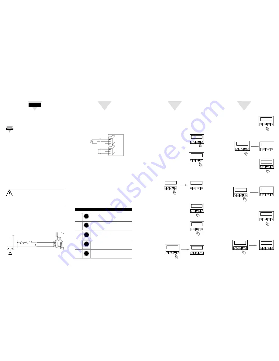
Wiring a Current Transmitter
Follow these steps to wire a current input sensor with
sensor excitation.
1. Locate connectors P3 & P9 on the right-side-rear of the unit.
2. Attach the wires and tighten the retaining screws. Tug
gently on the wires to verify the connection.
Wiring Example: Current Input with Sensor Excitation
3. Apply ac power. The front panel of the unit flashes RESET2.
If it does not:
a. Remove ac power.
b. Verify the P1 power and P3 and P9 input connections.
c. Check your power source.
d. Check your signal source.
4. Replace the rear cover. Thread the sensor wires through
the slots on the side of the cover. Replace the rear cover
screw.
5. Apply ac power once again.
Configure the Meter
Use the front panel buttons to access the configuration
menus, to either verify or set the unit values. The function
of each button is described below:
Meter Button Descriptions
Press This Button To:
sequentailly recall previous setpoint
settings (run mode only), store new
setpoint values.
access the configuration program
menus and move from one menu
to the next.
enter and scroll through a submenu.
change the value of a submenu.
move backward one menu (press
once) or exit the configuration
menus (press twice).
N/C
+S
–S
P9
1
2
3
1
2
3
P3
N/C
RTN
(+)
(
-
)
(4-20mA)
+E
–E
JUMPER
USER
PROVIDED
Quick Start Setup
Quick Start Setup scales your meter to read 0 to 100.0 for a
4 - 20mA input. This setup procedure is actually a series of
short tasks. To complete Quick Start Setup successfully, it
is important to perform all tasks in the order outlined in the
Quick Start Setup.
Select Input Range
1. Press MENU until the meter displays:
2. Press
/MIN until the meter flashes:
Press MENU and “CURRNT” stops
flashing.
Press
/MIN to display a flashing
input range of 4-20mA or 0-20 mA.
Press
/MAX until the meter displays
“4-20mA.”
3. Press MENU. The meter stores changes (if applicable),
then displays “RDG.CNF”:
Set Up Reading Configuration
1. Press
/MIN to display “RDG.1”.
Press
/MAX until the meter displays
“RDG.1=0”. Selecting “RDG.1=0”
enables direct formatting.
2. Press
/MIN to display “RDG.2”.
Press
/MAX until the meter displays
“RDG.2=1”. Selecting “RDG.2=1”
enables an active decimal point.
3. Press MENU. The meter stores changes (if applicable),
then displays “RDG SC”:
Set Reading Scale Factor and Reading Offset
1. Press
/MIN to display the scale factor
value. Change the value, if necessary,
to read “1.00000” (Use
/MIN to scroll
through digits and
/MAX to change
the digit’s value).
2. Press MENU. The meter stores changes (if applicable)
then displays “RDG.OF”:
3. Press
/MIN to display the offset value.
Change the value, if necessary, to read
“000000” (Use
/MIN to scroll
through digits and
/MAX to change
the digit’s value).
4. Press MENU. The meter stores change,
if applicable, then displays “IN CNF”.
Set Default Input Scale and Offset
1. Press
/MIN until the meter flashes.
Change the value, if necessary, to read
“INP.6=0” (Use
/MIN to scroll
through INP submenu choices and
/MAX to select 0 as the value). Setting
“INP.6=0” disables input scale and offset.
2. Press MENU. The meter stores changes, if applicable,
then displays “IN.SC.OF”.
2
3
4
START HERE
/MIN
/MAX
RESET
MENU
SETPTS
1.00000
SETPTS
/MAX
/MIN
MENU
RESET
stored
SETPTS
/MAX
/MIN
MENU
RESET
IN.SC.OF
SETPTS
/MAX
/MIN
MENU
RESET
stored
SETPTS
/MAX
/MIN
MENU
RESET
rdg.of
SETPTS
/MAX
/MIN
MENU
RESET
000000
SETPTS
/MAX
/MIN
MENU
RESET
stored
SETPTS
/MAX
/MIN
MENU
RESET
CNTBY
SETPTS
/MAX
/MIN
MENU
RESET
INp.6=0
SETPTS
/MAX
/MIN
MENU
RESET
stored
SETPTS
/MAX
/MIN
MENU
RESET
rdg sc
SETPTS
/MAX
/MIN
MENU
RESET
INPUT
SETPTS
/MAX
/MIN
MENU
RESET
CURRNT
SETPTS
/MAX
/MIN
MENU
RESET
RDG.2=1
SETPTS
/MAX
/MIN
MENU
RESET
stored
SETPTS
/MAX
/MIN
MENU
RESET
rdg.CNF
SETPTS
/MAX
/MIN
MENU
RESET
RDG.1=0
SETPTS
/MAX
/MIN
MENU
RESET


