http://www.omega.com
e-mail: [email protected]
®
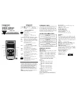
User’s Guide
DP116-RTD
MINIATURE PANEL
THERMOMETER
USA
MADE
IN
Summary of Contents for DP116-RTD
Page 8: ...vi NOTES...
http://www.omega.com
e-mail: [email protected]
®
User’s Guide
DP116-RTD
MINIATURE PANEL
THERMOMETER
USA
MADE
IN
Page 8: ...vi NOTES...