


omega.com
e-mail: [email protected]
For latest product manuals:
omegamanual.info
User’s Guide
M-4590/1107
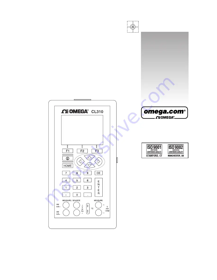
CL310
Shop online at
omega.com
e-mail: [email protected]
For latest product manuals:
omegamanual.info
User’s Guide
M-4590/1107
CL310
Shop online at