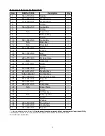
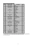
Omega Lift 13120 Operating Instructions & Parts Manual Download Page 4

4

Possible Causes

Corrective Action

Jack will not pressurize

Jack *bleeds off after lift
* 'bleeds off' means load slowly and 

unintentionally lowers after lifting

While lowering, fluid leaks from

reservoir area

Jack saddle will not descend to low

-

est advertised height 

Ram plunger will not remain lowered 

after released from contact with load 
(creeps back up)

Poor lift performance

 Will not lift to full extension

•  Release valve not tightly closed
•  Load is too heavy

•  Hydraulic unit malfunction

•  Reservoir overfilled
•  Ram plunger/cylinder deformed, 

seized up in ram cylinder and/or 
top nut, likely the result of off-
center loading

•  Air trapped in system

•  Fluid level low
•  Air trapped in system

•  Hydraulic unit malfunction

• Fluid level low

•  Ensure release valve tightly closed
•  Consider higher capacity jack

•  Contact Service Center

•  Drain fluid to proper level
•  Contact Service Center

•  Follow the Owners Manual instructions 

for bleeding air from system.

• Ensure proper fluid level
•  Follow the Owners Manual instructions 

for bleeding air from system.

•  Contact Service Center

• Ensure proper fluid level

TROUBLESHOOTING 

Symptom

MAINTENANCE

Important

: Use only good grade hydraulic jack oil. Avoid mixing different types of fluid and 

NEVER

 use brake fluid, turbine oil, 

transmission fluid, motor oil or glycerin. Improper fluid can cause premature failure of the jack and the potential for sudden and 
immediate loss of load. We recommend Mobil DTE13M or equivalent.

Storage

Store the jack with pump piston, ram plunger/saddle fully lowered and release valve open, but never more than 1 

turn. This will 

help prevent rust and corrosion to those critical surfaces.

Cleaning

Periodically check the pump piston and ram plunger/saddle for signs of rust or corrosion. Clean as needed and wipe with a clean, 

oil soaked rag.

Lubrication 

 A periodic coating of light lubricating oil to pivot points will help to ensure that pump piston linkages move freely.

Note:

 Never apply oil to saddle.

Changing oil

For best performance and longest life, replace the  complete fluid supply at least once per year.

1. With saddle fully lowered set jack in its upright, level position. Locate and remove oil filler plug/screw.
2.  Lay the jack on its side and drain the fluid into a suitable container.

 
Note:

 Dispose of hydraulic fluid in accordance with local regulations.

3. Fill with oil even with the bottom of the oil filler hole. Reinstall the oil filler plug/screw.

Adding

1. With saddle fully lowered set jack in its upright, level position. Locate and remove oil filler plug/screw.

2

. Fill with oil even with the bottom of the oil filler hole. Reinstall the oil filler plug/screw.

•  The paint on this product contains lead, a chemical 
known in the State of California to cause cancer, birth 
defects and other reproductive harm.  
•  Do not ingest paint chips and keep product away from 
children.  
•  Wash hands after each use.

WARNING


!

Paint contains lead!
DO NOT sand or grind painted surface!


!

Summary of Contents for 13120

Page 1: ...der y seguir las instrucciónes antes de utilizar el aparato El manual de instrucciónes y la información de seguridad deben estar comunicado en lengua del operador antes del uso No seguir estas indicaciónes puede causar daños personales o materiales WARNING To avoid crushing and related injuries NEVER work on under or around a load supported only by a hydraulic jack ALWAYS use adequately rated jack...

Page 2: ...intended load contact point is able to withstand the load applied by this jack 1 Before using this product read the owner s manual completely and familiarize yourself thoroughly with the product its components and recognize the hazards associated with its use 2 To familiarize yourself with basic operation use the operating handle to engage and turn the release valve a Clockwise until firm resistan...

Page 3: ...r thread engagement 3 Pump until load reaches desired height Immediately secure with appropriately rated mechanical devices It is recommended you follow the load with cribbing and blocking where practical Never allow personnel to work or pass under a load until the load is secured by cribbing blocking or other mechanical means Lowering Make certain that all personnel are clear of the load before l...

Page 4: ...al for sudden and immediate loss of load We recommend Mobil DTE13M or equivalent Storage Store the jack with pump piston ram plunger saddle fully lowered and release valve open but never more than 1 turn This will help prevent rust and corrosion to those critical surfaces Cleaning Periodically check the pump piston and ram plunger saddle for signs of rust or corrosion Clean as needed and wipe with...

Page 5: ...igure 2 Replacement Parts Illustration for Model 13060 Replacement Parts Illustration for Model 13060 9 35 17 6 4 5 8 10 16 7 11 3 23 26 27 24 29 30 31 32 34 28 25 2 2 33 22 21 20 19 1 15 14 13 12 18 12 12 ...

Page 6: ...e Cap 1 19 414 6 1215 307 Screw 1 20 O ring 1 21 512 2 0067 010 Spring 1 22 414 6 1216 107 Needle Valve 1 23 505 9 0092 207 Oil Filler Plug 1 24 226 3 1300 102 Handle Sleeve Assy 1 25 511 5 0012 016 Snap Pin 2 26 518 4 0070 307 Pin 2 27 226 4 1415 105 Pump Assy 1 28 N A Pump Piston 1 29 O ring 1 30 Oil Seal Assy 1 31 N A Pump Cylinder 1 32 O ring 1 33 Washer 1 34 226 6 1402 108 Swivel Seat 1 35 18...

Page 7: ...7 Replacement parts illustration for Model 13120 Figure 3 Replacement Parts Illustration for Model 13120 1 2 3 4 5 6 7 8 9 10 11 12 27 26 25 24 23 22 21 14 13 19 20 15 16 17 18 2 ...

Page 8: ...dle Sleeve Assy 1 15 511 5 0012 016 Snap Pin 2 16 518 4 0070 307 Pin 2 17 505 9 0092 207 Oil Filler Plug 1 18 A20 4 1500 106 Hyd Cartridge Assy 1 19 Oil Seal 1 20 238 6 1701 403 Release Valve 1 21 226 4 1415 105 Pump Assy 1 22 N A Pump Piston 1 23 O ring 1 24 Oil Seal Assy 1 25 N A Pump Cylinder 1 26 O ring 1 27 266 2 1402 108 Swivel Seat 1 186 3 9906 107 Seal Kit 1 Items available only as Seal Ki...

Page 9: ...9 Replacement parts illustration for Model 13200 Figure 4 Replacement Parts Illustration for Model 13200 ...

Page 10: ... 2 17 O ring 1 18 N A Oil Filler Screw 1 19 324 4 1900 208 Oil Filler Screw Assy 1 20 A20 4 1500 106 Hyd Cartridge Assy 1 21 Oil Seal 1 22 238 6 1701 403 Release Valve 1 23 226 4 1415 105 Pump Assy 1 24 N A Pump Piston 1 25 O ring 1 26 Oil Seal Assy 1 27 N A Pump Cylinder 1 28 O ring 1 29 226 6 1402 108 Swivel Seat 1 30 181 3 2100 103 Handle Assy 1 226 3 9906 108 Seal Kit 1 10 Replacement Parts Li...

Page 11: ...E OR LOSS WHATSOEVER 3 ANY IMPLIED WARRANTIES INCLUDING WITHOUT LIMITATION THE IMPLIED WARRANTIES OF MERCHANTABILITY AND FITNESS FOR A PARTICULAR PURPOSE SHALL BE LIMITED TO ONE YEAR OTHERWISE THE REPAIR REPLACEMENT OR REFUND AS PROVIDED UNDER THIS EXPRESS LIMITED WARRANTY IS THE EXCLUSIVE REMEDY OF THE CONSUMER AND IS PROVIDED IN LIEU OF ALL OTHER WARRANTIES EXPRESS OR IMPLIED 4 ANY MODIFICATION ...

Page 12: ...12 Contact SFA Companies 10939 N Pomona Ave Kansas City MO 64153 U S A Tel 888 332 6419 Fax 816 891 6599 E Mail sales omegalift com Omega Website http www omegalift com Note Page ...

Reviews: