background image

Appendix C

Configuration Aspects for Programmers

NetScan User’s Manual

C-3


Measuring Modes


Overview


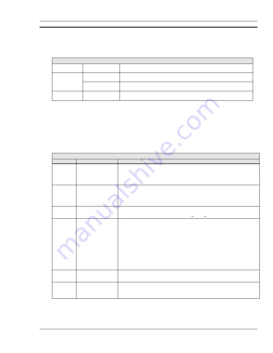
You can select either of two scanning modes for NetScan, 1) Normal mode or 2) High-speed, single channel
mode
.


NetScan Measuring Modes


Mode


“Average weight”
Setting


Application


Normal


16, 32, 64, 128, or
256


Recommended for AC noise rejection.


1, 2, 4, or 8


Recommended for high-speed, multiple channel applications for thermocouples
and DC voltages where noise filtering is not an issue.


High-speed,
single-channel


not selectable


High-speed, single channel applications for AC and DC voltage post-acquisition
waveform analysis


In the Normal mode, NetScan samples channel data at 1.92 kHz, or once every 520.83 µs.  You can select the
average weight (number of samples to average) to provide noise filtering, as discussed later in this section.


In the High-speed, single channel mode, NetScan collects data in user-defined multiples of 256 samples at a
sampling frequency within the range of 38.5 Hz to 20.0 kHz.


Aside from selecting NetScan’s scanning mode, and setting the mode parameters from ChartView software (see
Chapter 4, ChartView Software Reference), the following commands can be used.  Note that Appendix A
contains more detailed information regarding these commands.


Mode-Related Parameter Commands


Command


Syntax


Function


M#


M#mode


Set Measuring Mode.


Options for mode are:


0

 - Normal mode, and


1

 - High-speed, single channel mode.


W#


W#wt


Set Averaging Weight.


Specify the number of samples to average in Normal mode, where 

wt

 is the

averaging weight.  Options for

 wt

 are: 1, 2, 4, 8, 16, 32, 64, 128, and 256, with 32

being the default.


F#


F#freq


Set frequency for High-speed, single channel mode.


freq

 must be a value for Hz such that  38.5 < 

freq

 < 2000.  The default is 2000 Hz.


Y


Ypre,post,stop


or


Y0,count,0


Set Counts or Select Blocks.


In Normal mode - This command is used to set acquisition counts where 

pre

 is the

pre-trigger count, 

post

 is the post-trigger count, and 

stop

 is the post-stop count.


In High-speed, single channel mode (burst mode) the 

post

 position serves as count.

count is used to select the number of 256 sample blocks to be collected.  Options for
block count are dependent upon system memory as follows:


256Kbytes, count value allowed is: 2 to 512


1 Mbyte, count value allowed is:  2 to 2048


4 Mbytes, count value allowed is:  2 to 8192


8 Mbytes, count value allowed is:  2 to 16384


Note:  In each case the number assigned for block count must be a power of 2.


U16


M#modeF#freqW#wt


Query the Measuring Mode.


This command queries the following three parameters: 

M#

F#

, and 

W#

.


U17


U17


Return RMS.


This command computes and returns the root mean square (RMS) value of the last
completed high-speed, single-channel mode acquisition.


Summary of Contents for OMB-NETSCAN 1500

Page 1: ...OMB NETSCAN Ethernet Internet Based Data Logging Control Instrument User s Guide p n OMB 1035 0901 Rev 1 0...

Page 2: ...311114 France 9 rue Denis Papin 78190 Trappes Tel 33 130 621 400 Toll Free in France 0800 4 06342 e mail france omega com FAX 33 130 699 120 Germany Austria Daimlerstrasse 26 D 75392 Deckenpfronn Germ...

Page 3: ...lines external TTL connectors signal conditioning modules CSN Exp expansion chassis option and high current CSN relay card option Appendices The Appendices provide programming related information that...

Page 4: ...4 2 What ChartView and ChartView Plus Provide 4 3 Main Window 4 4 Channel Information Region 4 6 Status Indicator Region 4 7 Main Window Toolbar 4 8 Group Select 4 8 Start Pause and Stop Charts 4 8 Sc...

Page 5: ...ply Fuse 7 4 Memory Configuration 7 4 Expanded Memory Options 7 4 Calibration Memory Write Enable Disable 7 6 Ethernet Interface Configuration 7 6 RS 232 422 Interface Configuration 7 6 Configuring RS...

Page 6: ...iv NetScan User s Manual...

Page 7: ...for Windows95 98 32 Mbytes recommended Overview This chapter explains how to configure NetScan for ethernet use The chapter provides steps for making proper connection to the ethernet and includes po...

Page 8: ...ltage of your intended AC power supply If you need to change the voltage selection for any reason refer to Chapter 7 s section entitled Power Aspects Changing the Voltage Setting Verify DIP Switch Set...

Page 9: ...o could cause equipment damage due to electrostatic discharge 87 21 Only one CSN Relay card can be used in a NetScan system Attempts to install the CSN Relay card in a slot other than slot 1 of NetSca...

Page 10: ...cable 2 If connecting NetScan to a hub connect a straight through type 10 Base T type ethernet cable CA 192 5 to NetScan s ETHERNET Port then connect the other end of the cable to the PC s ethernet h...

Page 11: ...actory default settings or a user defined configuration Loads appropriate registers with corresponding values in NV RAM Checks a flag to see if alarms should be enabled at power up and if so enables t...

Page 12: ...h a computer via the ethernet The NetScan Configuration Utility application completes this task by sending configuration settings from your computer s serial port to the configuration port CONFIG on N...

Page 13: ...al software installation prompts as applicable to your application Note After you have finished using the NetScan Configuration Utility to complete your unit s address settings you can remove the DB9...

Page 14: ...dress The IP Internet Protocol is a device address that is unique to one specific device located on the network A device s IP address can not be shared by any other device on the network The only rest...

Page 15: ...dress 2 The sub net mask should be set to 255 255 255 0 3 The gateway address can be omitted Example TPC IP address set to 192 88 247 1 Sub net mask set to 255 255 255 0 2 Private Local Area Network L...

Page 16: ...e s of cards used your connections will be made via one or more of the following screw terminal mini plug BNC or safety jack type input connector Reference Note Chapter 7 contains information regardin...

Page 17: ...ctively Outputs 1 through 16 can be used with the relay card option Chapter 7 contains additional information DB50 Pin Descriptions Output Signal Pin No Output Signal Pin No Input Signal Pin No 1 1 17...

Page 18: ...1 12 Configuring and Starting NetScan NetScan User s Manual Notes...

Page 19: ...s will help you master ChartViewNET more quickly and should be understood before proceeding with the tutorial ChartViewNET refers to a ChartView program that has the network feature of the program act...

Page 20: ...sent a feature called Chart Setup Wizard is automatically activated to assist you with your setup To make the best use of Chart Setup Wizard you need to understand the relationship of Groups Charts an...

Page 21: ...lues from the channel configuration dialog box 3 Chart channels and or use meters while acquiring data to disk Prior to using ChartView for charting and or meter use while simultaneously acquiring dat...

Page 22: ...own menu or Chart Setup Dialog Box 7 Display Configuration or Pointer over chart and right click Current group will be selected 20 Divide 2 or Tab to and hit Spacebar 8 Channel Configuration 21 Time S...

Page 23: ...pull down menu Acquisition Parameters Check the acquisition parameters via the Acquisition Configuration window This window can be accessed through the Setup pull down menu Data File Parameters Check...

Page 24: ...mulated Instrument mode This mode provides a means of running ChartView and inspecting its features without hardware concern Note that you can change the interface mode at anytime during a configurati...

Page 25: ...ated in the previous note only ChartView Plus allows the use of multiple groups and overlapping channels You can choose to manually create a configuration or have one created automatically In addition...

Page 26: ...up 2 Chart 1 CH1 CH2 CH3 CH4 Chart 1 CH13 CH14 CH15 CH16 Chart 2 CH5 CH6 CH7 CH8 Chart 2 CH17 CH18 CH19 CH20 Chart 3 CH9 CH10 CH11 CH12 Chart 3 CH21 CH22 CH23 CH24 By using the mouse arrow and clickin...

Page 27: ...n obtaining On indicating enabled or Off indicating disabled You can also use a pull down list which appears for enable disable See Chapter 4 if more detail is needed Channels set up for your display...

Page 28: ...ower 7 Display Configuration 8 Channel Configuration 9 PostView 10 Arm Acquisition 11 Disarm 12 Print Charts ChartView Toolbar Reference The information entered in the Acquisition window is used by th...

Page 29: ...en in Normal Mode Values of 1 2 4 and 8 are for high speed multiple channel applications for thermocouples and DC voltages where noise filtering is not an issue Values of 16 32 64 128 and 256 are reco...

Page 30: ...rs 3 Pause Charts 4 Stop Charts 5 Scroll Faster 6 Scroll Slower 7 Display Configuration 8 Channel Configuration 9 PostView 10 Arm Acquisition 11 Disarm 12 Print Charts ChartView Toolbar Reference 8 St...

Page 31: ...nd can easily be expanded up to 128 channels with the use of an expansion module NetScan is well suited for temperature and voltage measurements requiring channel to channel isolation This isolation i...

Page 32: ...digital inputs Two programmable scan rates 1 a programmable scan rate for pre trigger and post trigger sampling and 2 a programmable scan rate for accelerated sampling on event detection A built in re...

Page 33: ...92 Adapter 10 Base T ethernet cross over adapter Additional Hardware Options 4 slot expansion chassis Memory expansion options 1 Mbyte 4 Mbyte or 8 Mbyte 16 output CSN Relay card NetScan Specification...

Page 34: ...H at 40 C Control Power Switch Ethernet or RS 232 422 option handshake parity baud rate calibration memory write enable disable Rear Panel LED Indicators ALARM TRIGGER SCAN ERROR and POWER SEND and RE...

Page 35: ...tables based on the IPTS 68 standard as listed with the US Department of Commerce NTIS International Electrotechnical Commission IEC 43 760 Trigger Input Connector External BNC connector Trigger Outp...

Page 36: ...nections to device including the AC line and analog inputs must be disconnected prior to opening the NetScan main unit or the expansion chassis Internal voltage potentials exist which could cause bodi...

Page 37: ...ncluding calibration equipment requirements for the following NetScan main unit calibration for offset and gain Offset calibration for all card types Gain calibration for low volts cards Gain calibrat...

Page 38: ...3 8 General Information and Specifications NetScan User s Manual Notes...

Page 39: ...Chart Setup Wizard 4 41 Introduction 4 41 Automatic Chart Setup with Wizard 4 42 Bypassing Automatic Chart Setup 4 43 Reference Note This chapter serves as a reference for ChartView ChartView Plus Ch...

Page 40: ...harts and channels This aspect of configuration is performed through Chart Setup Wizard discussed in the following text or through a Chart Setup window accessed through the Channel Configuration butto...

Page 41: ...cted display channels can be viewed Acquisiton Device Acquisiton Device Acquisiton Device Sensor H ard Disk H ard Disk H ard Disk H ard Disk What ChartView and ChartView Plus Provide ChartView and Cha...

Page 42: ...d spacebar are control options that allow you to tab to a field and make changes with the specified control Channel Selection 14 can also be made by tabbing to the Center Control 17 or Units Div Contr...

Page 43: ...down menu or Chart Setup Dialog Box 7 Display Configuration or Pointer over chart and right click Current group will be selected 20 Divide 2 or Tab to Spacebar 8 Channel Configuration 21 Time Stamp hr...

Page 44: ...of a special code allowing up to four overlapping channels per chart Regardless of whether you are using the basic ChartView program or ChartView Plus there is a maximum limit of 16 charts per group M...

Page 45: ...ce Several sample messages appear below Sample Status Messages Attaching to device Trigger device Setting acquisition parameters Setting channel configuration Acquisition active Updating active Settin...

Page 46: ...the desired group The group list can be obtained by any of the control options provided in the table on page 4 5 These are a clicking the down arrow b using Ctrl G on the keyboard c using the keyboar...

Page 47: ...Chapter 2 Additional Chart Setup Wizard information begins on page 4 41 The method you use to access the Display Configuration Setup window makes a difference When you use the toolbar button or the pu...

Page 48: ...of each other then the channels listed lower in the display list the most recently added channels will obscure the channels higher in the list those that were added first Adding Channel 2 to Chart 1...

Page 49: ...l is selected Units Div is the vertical value of on chart grid increment When you change Y Center or Units Div Y Max and Y Min are automatically adjusted You can not directly adjust Y Max or Y Min whi...

Page 50: ...e of the Chart Setup Wizard s automatic methods and then edit the setup To manually setup your chart display using the clean slate approach as opposed to editing an existing display perform the follow...

Page 51: ...tton The Display Configuration Setup screen changes to show chart groups and the number of charts for the selected black highlighted chart group From this screen you can change the number of charts in...

Page 52: ...ld delete the channel from Chart1 Note When a chart contains overlapping channels and the channels share values such that their traces reside on top of each other then the channels that are listed low...

Page 53: ...w post acq data viewer The PostView post acquisition data viewer button accesses the PostView program This independent program allows you to view waveforms recorded by data acquisition programs such a...

Page 54: ...annel configuration settings for later recall The Save command overwrites the existing version if the versions are named the same Save As Saves the existing configuration for later recall asks whether...

Page 55: ...w is shutdown the selected interface device and all channel configuration settings will be automatically saved in a default configuration file Upon the next start of ChartView the default configuratio...

Page 56: ...Chart 2 you could use Zoom to view Chart 2 using the full chart viewing area as compared to using one third of the area The zoom feature can also be invoked by double clicking in the chart region of t...

Page 57: ...ystem timeout value indicated in the above figure will be overridden by the timeout value in the DDE Configuration for Excel dialog box accessed from the Data pull down menu Acquisition PostView Comme...

Page 58: ...ed by up to 2 seconds after the previous acquisition has finished Acquire Arm Acquisition Ctrl T Arms the data acquisition device in preparation of receiving a trigger Disarm Ctrl Y Disarms the data a...

Page 59: ...ition is completed a dialog box will ask if you want to return to origin If you select Yes you will have an overwrite on the Excel spreadsheet starting with the existing column and row designation If...

Page 60: ...iew s Window pull down menu brings up the Analog Meters window This window displays several channels in a dial gage format To activate the display select the Start button in the meter toolbar At least...

Page 61: ...nd be named WAVE NetScan devices can not make use of the IEEE 488 interface Setup RS 232 422 The RS 232 422 Setup dialog box appears If Yes is chosen for modem the RS 232 422 Setup window changes allo...

Page 62: ...atus Brings up the Alarm Status box The Alarm Status box shows the current state of each alarm The alarm state appears as either a 1 or 0 the 1 being digital High and the 0 being digital Low 0 A one f...

Page 63: ...e channel information if you have selected not to save Alarm ID s The following example shows what the Alarm log entries look like if this configuration is selected 1 21 10 PM 10 29 98 000000000000000...

Page 64: ...log box You can adjust the time and date settings from this box Device Status Dialog Boxes Device Configuration A Device Expanded Menu obtained with use of the F12 Key You can expand the Device pull d...

Page 65: ...ens windows or dialog boxes other than the main chart screen ChartView s main window After a brief discussion and illustration of each meter type commonalties to these three types of meters is present...

Page 66: ...the right mouse button in this same area brings up a configuration pop up menu item H Both of these pop up menus are discussed in the section Meters Configuration Menu The items in this window are as...

Page 67: ...aph Meters figure item H Both of these pop up menus are discussed in the section Meters Configuration Menu Note that Meter 3 CH3 in the above figure shows Peak Indicators near the pointer as well as a...

Page 68: ...rument used TempScan MultiScan ChartScan or NetScan Double clicking the left mouse button in a meters scale area brings up a channel selection pop up menu not shown A single click with the right mouse...

Page 69: ...ers D Stay On Top Push pin Locks or unlocks the meter window on top of other windows E Print Sends the meter s display image to connected printer F Rows x Columns Opens a small menu with row x column...

Page 70: ...he desired meter group Bar Graph Analog or Digital 2 Place the mouse cursor over the meter you desire to reconfigure 3 Click on the right mouse button A Meters Configuration Menu similar to that in th...

Page 71: ...y as well as select Misc to Show Trend Indicator and Show Peak Hold Indicators You can use the Simulated Instrument mode to familiarize yourself with various meter configuration options Setup Window T...

Page 72: ...g table indicates message and pull down menu aspects of the Channel and Alarm Setup Dialog Box The pull down list selection or copy paste process are useful for making multiple channel configuration c...

Page 73: ...st be unique specific to its designated channel 6 Units Cells in the Units column are dependent on the Type selected and automatically change when the type is changed for example temperature units wil...

Page 74: ...limited to a proportionality constant or gain factor but not zero b is the offset value the value of the calculated reading when the scanned value is zero Alarm Configuration Columns 1 Low Limit Set...

Page 75: ...in the table on the following page In the High speed single channel mode the Scan Intervals parameters section is replaced with a High Speed Setup parameters section with boxes for selection of Chann...

Page 76: ...MultiScan ChartScan or NetScan is connected and High Speed Single Channel Burst Mode is selected then Count from trigger is the only Stop available for the event configuration Count Specify a number o...

Page 77: ...ey areas of the Data Destination box If you have ChartView Plus you can use the lower section of the Data Destination box to configure Auto Re arm as described in the sub section below entitled Auto R...

Page 78: ...se to repeat 100 or more acquisitions with this same trigger criteria Channel 1 30 C Whether you select to capture the trigger blocks in one file or each in a separate file each of the data acquisitio...

Page 79: ...iew Plus can be activated by use of a special code available from the factory Please consult your service representative for more detailed information Activating the Chart Setup Wizard from the Chart...

Page 80: ...6 charts Up to 4 overlapping channels per chart Advanced 1 Up to 64 groups Up to 16 charts per group Up to 4 overlapping channels per chart Note 1 Moderate and Advanced modes of Automatic Chart Creati...

Page 81: ...ling additional channels then click on the OK button After clicking OK the Main Window appears and you can begin running charts The Channel and Alarm Setup section of this chapter contains related inf...

Page 82: ...4 44 ChartView Software Reference NetScan User s Manual Notes...

Page 83: ...on of the file format must be completed before PostView can access the data A further explanation follows Personal DaqView DaqView LogView and WaveView create raw binary bin formatted files during the...

Page 84: ...bsolute Default is relative time stamp 8 Show Grid Ctrl G 19 Scroll 9 Show Markers Ctrl K 20 Access Chart Setup Right click to access edit menu for selected chart and channel 10 Chart Max Scale Value...

Page 85: ...ot or txt filename extensions 2 Note PostView automatically checks for Display Configuration files These files are automatically saved when exiting your data acquisition program These files are recogn...

Page 86: ...options 5 Zoom Out The Zoom Out button doubles the visible timebase showing more of the waveform For example if 10 seconds of information is visible clicking the Zoom Out button will show 20 seconds...

Page 87: ...tabbing over to the control Making changes to a channel s chart parameters does not affect the parameters of the other channels with the following exception Holding the keyboard s control key down whi...

Page 88: ...the chart region Absolute time Ctrl A Places the timebase in a 24 hour absolute time format For example 25 2 seconds after 3 08 p m would appear as 15 08 25 2 Also see PostView Timebase page 15 Relati...

Page 89: ...e PostView s initial chart display configuration with an automated or manual method When PostView can not locate a display configuration file it automatically accesses the Chart Setup Wizard feature I...

Page 90: ...etup Type Group Setup for Chart Groups Chart Setup Channel Setup Simple 1 group only Up to 16 charts 1 channel per chart Moderate 1 group only Up to 16 charts Up to 4 overlapping channels per chart Ad...

Page 91: ...ed Note that only one group of charts can be viewed at a time Display Configuration Note When PostView does not find a display configuration file it automatically opens the Chart Setup Wizard You can...

Page 92: ...in the example From this setup box you can add or delete charts and channels You can Use the Shift or Ctrl key in conjunction with the cursor to select several channels for addition or deletion doubl...

Page 93: ...or Units Division while Units Full Scale is selected You can change Y Max and Y Min by using the up and down arrows or by highlighting the existing value typing in the new value the pressing Enter on...

Page 94: ...ic elements such as Automatically Add Groups to the Setup Perform the following steps to manually create your chart display 1 From the Chart Setup Wizard window select Manual Chart Creation Create Cha...

Page 95: ...here are four methods of adding channels These are as follows Highlight an available channel using the cursor and left hand mouse button then click the Add button Repeat for each channel to be added D...

Page 96: ...in These are the upper and lower limits of the Channel as they will appear on the chart when the channel is selected When you change either parameter Y Center and Units Division are automatically adju...

Page 97: ...he type of timebase desired absolute or relative no user action is required in regard to the timebase display Two Points About the PostView Timebase When a data file is loaded into PostView for the ve...

Page 98: ...with negative time numbers If post stop data is available scans collected after the Stop Event they are displayed after the Stop Event marker If a dual timebase was used when collecting the data Post...

Page 99: ...structions presented later in this chapter Note that this chapter has been written for both ChartScan and NetScan devices Note The main unit ChartScan or NetScan and signal conditioning cards are cali...

Page 100: ...rage of Calibration Constants To preserve calibration constants main unit constants are stored in an on board battery backed up RAM and the constants for each signal conditioning card are stored on th...

Page 101: ...Application ScanCal s Main Window Select the ScanCal option from the ChartView Program Group ScanCal s Main Window will appear The window contains pull down menus a toolbar and calibration instructio...

Page 102: ...mmunications prior to performing calibration Refer to your hardware setup chapter as needed 1a Select the DIP Switch toolbar icon to activate the Interface Parameters window This allows you to select...

Page 103: ...a new password can be entered after enabling the calibration mode This mode is enabled by indenting the Calibration Enable Disable Pushbutton After pushing in the button execute the K command to chan...

Page 104: ...ot slot 1 of the main unit 87 21 Do not install or remove any cards from the main unit or from its expansion chassis unless the unit is powered OFF and has no power sources connected to it 87 21 Use a...

Page 105: ...indicated in the NetScan figure page 6 2 6 If the calibration password has not been changed enter K12345 If the password has been changed enter the K command and new password This enables the calibrat...

Page 106: ...tion voltages Calibration Card installed in bottom slot slot 1 of main unit see required specifications on page 6 2 87 21 Offset calibration of main unit must be completed prior to calibrating the mai...

Page 107: ...ecision digital multimeter to verify voltage accuracy 6 Type G0 91X The Trigger LED will flash indicating that gain calibration is in progress When flashing stops the chassis gain calibration is compl...

Page 108: ...free work area and grounded wrist strap when handling circuit boards and electronic components Failure to do so could cause equipment damage due to electrostatic discharge 1 Ensure the main unit is p...

Page 109: ...ponse to U2X Indication for Calibration Mode U128 No error U129 Read Failure EEPROM Error U130 Write Failure EEPROM Error U132 Chksum Err EEPROM Error U136 Cal Err offset gain or temperature sensor ou...

Page 110: ...section entitled Gain Calibration for High Volts Cards beginning on page 6 15 87 21 The main unit chassis must be calibrated for offset and gain and the signal conditioning cards must be calibrated f...

Page 111: ...NetScan User s Manual Calibration 6 13 1 Connect an applicable calibration harness to each card Refer to figure below...

Page 112: ...e digit after the G is the channel number and the number immediately preceding the X assigns the voltage value e g G1 1X means Calibrate Gain for channel 1 50 mV 3 After each calibration type U2X and...

Page 113: ...ted for offset prior to calibrating the signal conditioning cards for gain 87 21 Do not install or remove any cards from the main unit or from its expansion chassis unless the unit is powered OFF and...

Page 114: ...Calibrate Gain for channel 1 2 5 V 3 After each calibration type U2X and check for a return of U128 to confirm no errors Response codes and meanings applicable to calibration are as follows Response...

Page 115: ...equired specifications on page 6 2 Note See figures Cold Junction Calibration Equipment Setup and Verification of Calibrated Temperatures The cold junction calibration applies only to thermocouple car...

Page 116: ...2 hours The cards to be calibrated including those in an expansion chassis if used should be installed prior to the 1 hour chassis warm up and should be in the slots in which they will be used during...

Page 117: ...e for each of the four CJC reference channels Repeat verification for all T C cards Note The Cold Cell Simulator in figure a shows a special connection box attached to it This connection box which can...

Page 118: ...6 20 Calibration NetScan User s Manual...

Page 119: ...ions 7 17 Expansion Chassis CSN Exp Option 7 17 Connecting the Expansion Chassis 7 17 Automatic Channel Assignment 7 19 Overview This section provides information regarding NetScan hardware The chapte...

Page 120: ...FF when the ethernet interface is disabled FLASHES when a problem exists that requires factory attention NetScan Rear Panel Item Description Power Connector Provides a means for connecting NetScan to...

Page 121: ...d to change the voltage selection complete the following steps 51 1 Never disassemble NetScan s case while it is connected to the AC power line Internal voltage potentials exist which could cause bodi...

Page 122: ...all other terminals disconnected If the line voltage selector is changed then the fuse designated for that line voltage must be used Replace the AC power supply fuse as follows 1 Turn NetScan s power...

Page 123: ...uding static free work area and grounded wrist strap when handling circuit boards and electronic components Failure to do so could cause equipment damage due to electrostatic discharge 1 Turn off the...

Page 124: ...f it is necessary to change the calibration password via the K command or to calibrate the chassis this hardware write protection can be disabled by pushing the calibration enable disable button so it...

Page 125: ...orner of NetScan s rear panel Default settings are as follows Note that micro switch 1 must be set to the 0 position The IEEE position does not apply to NetScan Selection COMM SELECT HANDSHAKE H S PAR...

Page 126: ...CONFIG is for ethernet configuration only The DB9 connector labeled RS 232 422 is for serial interface applications The serial port default is for the RS 232 connector configured as DTE Data Terminal...

Page 127: ...input is used as a hardware handshake line to prevent NetScan from transmitting serial data to an RS 232 or RS 422 device when it is not able to accept it When RTS CTS handshaking is selected NetScan...

Page 128: ...input voltages to the range of 0 0 to 5 3 volts All digital I O lines are referenced to digital ground pins see following table DB50 Pinout 87 21 Do not exceed the 0 0 to 5 3 volt levels described abo...

Page 129: ...TTL output signal is pulsed for 100 ms Refer to the following trigger timing diagram Signal Conditioning Cards NetScan and its expansion chassis can each house a quantity of 4 signal conditioning card...

Page 130: ...0 C 0 5 C 0 8 C 0 10 C 0 20 C Type K 100 to 1372 C 200 C to 100 C 0 6 C 0 8 C 0 10 C 0 20 C Type T 100 to 400 C 200 to 100 C 0 5 C 0 8 C 0 15 C 0 25 C Type E 100 to 1000 C 200 C to 100 C 0 7 C 0 9 C 0...

Page 131: ...signal for AC volts Note 3 For AC voltages where the frequency of the input signal is an integer multiple of the AC line cycle 1 with line cycle integration enabled Note 4 Specified for coupling impe...

Page 132: ...mber of Inputs 16 differential programmable by channel for input range Input Types 10V 5V 1V and 100mV Input Connectors Removable screw terminal blocks BNC or Safety Jacks Voltage Range Accuracy 1 and...

Page 133: ...al Filtering Used for AC line cycle noise rejection Selectable off 1 256 samples in a binary count Temperature Coefficient 0 01 C Input Impedance 10 M typical Input Bias Current 20 pA maximum Maximum...

Page 134: ...ays in each of the two groups It is important to stay within the group total current limitation regardless of the current ratings of the relay contacts or the plug in terminal blocks otherwise the cir...

Page 135: ...ls indicators input or output connections Connecting the Expansion Chassis A ribbon cable electronically connects the expansion chassis to the main unit No additional power or interface cables are req...

Page 136: ...56 C353 39 1 C352 PH501 Expansion Backplane Card Partial Located In Expansion Chassis Analog Backplane Card Partial Located In NetScan Main Chassis Connecting the Backplane Cards CA 154 Connects to PH...

Page 137: ...ot 2 Slot 3 Slot 4 NetScan 1 16 17 32 33 48 48 64 Expansion Chassis 65 80 81 96 97 112 113 128 The relay card if used must go in slot 1 of the main NetScan unit When the relay card is used there are o...

Page 138: ...sonnel with the unit disconnected from the NetScan unit and with all other terminals disconnected If the line voltage selector is changed then the fuse designated for that line voltage must be used In...

Page 139: ...explained Sections on the individual commands include their parameters types typical use related information and a sample program excerpt Appendix B Ethernet API provides ethernet related command inf...

Page 140: ...A ii NetScan User s Manual...

Page 141: ...Mode A 33 K Change Calibration Keyword A 13 N Set Event Mask A 34 P Adjust Calibration Card Pots A 13 O Set Digital Output A 35 R Power On Reset A 14 P Program Trigger Times A 36 S Power Up Settings...

Page 142: ...e separated by a comma or white space For example Q4 1 1 0 0 or Q 4 1 1 0 0 is appropriate Command Strings Commands may be sent individually or in a string with other commands For example the followin...

Page 143: ...red to An example of a deferred command is Set Data Format F which determines the input and output format used for channel data when X is interpreted As deferred commands are interpreted their desired...

Page 144: ...on Mode Immediate E Error Status Query Immediate F Set Data Format Deferred F Set Burst Mode Frequency Deferred G Calibrate Channel Gain Immediate H Calibrate Channel Offset Immediate I Set Scan Inter...

Page 145: ...et User Terminator 2 Q Set Query Terminator 3 F Set Data Format 4 N Set Event Mask 5 L Set Trigger Level 7 Channel Setup Commands A Assign Alarm Output A Enable 1 or Disable 0 Alarm Stamping I Enable...

Page 146: ...sign to the digital output chans may be in two forms chan for a single channel where 1 chan max or first last for a range of channels where 1 first last max where max 128 for NetScan output is the dig...

Page 147: ...Calibrate the correction gain constants for given option card where chan is the channel number such that 1 chan max where max 128 for NetScan The chassis is chan 0 type is the channel type H Calibrate...

Page 148: ...the trigger start and or stop times for an acquisition configured for start and or stop on absolute time where start and stop are in the standard time date stamp format HH MM SS T mm dd yy where H is...

Page 149: ...R 1 Query the Status Byte Register STB 2 Query and clear Calibration Status Register CSR 3 Query system settings 4 Query current High Low Last registers 5 Query and clear current High Low Last 6 Query...

Page 150: ...affect instrument calibration Channel Refers to those commands which affect channel configuration and or acquisition System Refers to those commands which affect general system functionality Execution...

Page 151: ...0X Configure an acquisition with both start and stop trigger being Trigger On command PRINT 1 X Start the acquisition SLEEP 10 Wait 10 seconds to collect data PRINT 1 X Stop the acquisition B Flush Ac...

Page 152: ...Restore Factory Defaults F command may be used to restore the unit to the same configuration it had when it left the factory Issuing this command will cause the unit to load the factory default confi...

Page 153: ...ion Mode Keyword 12345 PRINT 1 U2X Check for Keyword Error INPUT 1 A C VAL A Get the Calibration Status Register IF C AND 16 THEN PRINT ERROR INVALID KEYWORD SLEEP 5 If so wait until keyword check jum...

Page 154: ...e to be 0 will cause the unit to load its last known configuration when it is powered on or when the Power On Reset R command is issued The last known configuration will be exactly the same as the con...

Page 155: ...u attempt to use it in conjunction with continuous gap free acquisitions with two timebases In addition time stamping is not valid in burst mode Note If the output format is binary instead of ASCII th...

Page 156: ...e back panel of the unit by using the A command to assign the channel to digital output This signal can be used to set off an audible alarm or signal another device of the occurrence of the alarm cond...

Page 157: ...tes will be appended as follows Byte 1 A07 A00 Byte 2 A15 A08 Byte 3 A23 A16 Byte 4 A31 A24 In Binary High Low mode 4 bytes will be appended as follows Byte 1 A15 A08 Byte 2 A07 A00 Byte 3 A31 A34 Byt...

Page 158: ...se of this fact defining the channel type is critical to the proper configuration of the channel Each channel must be assigned a channel type in order for it to be included in the scan group Likewise...

Page 159: ...n degrees Celsius Thermocouple Type Normal Operation Same as normal operation but without temperature sensor adjustment Without temperature sensor adjustment i e raw A D input of the T C type Temp sen...

Page 160: ...is with slot 5 being the bottom slot of the expansion chassis With optional Relay Card Installed installs in slot 1 Valid options for card are 0 Selects the chassis 1 selects card in slot 2 2 selects...

Page 161: ...es PRINT 1 T1 8 0 0X Arm the unit PRINT 1 X Trigger unit and collect scans E End Calibration Mode TYPE Calibration EXECUTION Immediate SYNTAX E Terminate Calibration Mode DESCRIPTION Note This command...

Page 162: ...Error occurs when the card calibration has failed or has been inappropriately calibrated E016 A Trigger Overrun Error occurs when more than one trigger event occurs for a given trigger state or when...

Page 163: ...eering Units Legend x ASCII digit h hour m minute s second mil see Note 2 MM month DD day YY year DDDDDDDD day Note 1 Binary Low Byte High Byte 1 and Binary High Byte Low Byte 2 are interpreted as eng...

Page 164: ...its and Counts Data output formats for command queries will follow the same rules as data input formatting As in the case of data input formats all readings output will be in Engineering Units unless...

Page 165: ...ency TYPE System EXECUTION Deferred SYNTAX F freq Select burst mode sampling frequency where freq is a real number and where 38 5 freq 20000 0 Hertz default DESCRIPTION The Set Burst Mode Frequency F...

Page 166: ...r the internal firmware to accurately interpret readings coming from the input channels This command will take the parameters chan and type and will calculate the gain based on the present channel inp...

Page 167: ...urately interpret readings coming from the input channels This command will take the parameter chan and calculate the offsets based on the present channel input voltage Note To achieve correct results...

Page 168: ...respectively The scan interval can be set to run as fast as the current unit configuration will allow This is referred to as fast mode Each of the two scan intervals can be configured as such by spec...

Page 169: ...indicates digital input on and 0 indicates digital input off In binary mode 2 bytes will be appended as follows Byte 2 00h I8 I1 In ASCII mode 8 bytes will be appended as follows DXXXD000 Where D Use...

Page 170: ...r time The function of the Calibrate Cold Junction Offset J command is to allow the adjusting of the internal firmware to compensate for the affects of component aging Since there are 4 cold junction...

Page 171: ...e issued The K command requires a pre defined keyword as a parameter This keyword must match the existing keyword definition in order to enter Calibration Mode If the keyword is not correct Calibratio...

Page 172: ...The parameter level is the value which if exceeded by going above or below it as defined should generate a trigger event The parameter hyst is the hysteresis value that with level is used to test whe...

Page 173: ...mples For AC Volts the root mean square RMS is computed over the specified number of samples High speed Single Channel Mode Burst mode is used to sample a single channel at a frequency specified by th...

Page 174: ...Sending this command allows the setting of the ESB when the pre defined stop event of a configured acquisition has occurred N004 Query Error This condition is set when an attempt is made to read data...

Page 175: ...ts such as if an alarm has been assigned to the output If it is desired to not affect a certain bank maybe because it is being used for alarm outputs a value of 999 can be used for the argument for th...

Page 176: ...r dates The values of the start and stop times are only used when the start and or stop events have been configured for Absolute Time If only the start time is needed the stop argument should be set t...

Page 177: ...in a pre defined format Any number of Query commands can be combined into one string to create a specialized status command that responds with only the information of interest for a given application...

Page 178: ...is argument specifies the terminator which will follow each scan that is output when a query request is made for Acquisition Buffer data When a query request is made for Acquisition Buffer data this t...

Page 179: ...channels for T C Type J PRINT 1 F0 0X Configure engineering units degrees C PRINT 1 Q7 7 0 0 0X Set the resp and hll terminators to LF EOI and the scan and block terminators to None PRINT 1 Q X Get th...

Page 180: ...perform their own calibration It is not necessary for normal everyday operation The information returned is as follows Card Number Serial Number Card ID type 16 TC Volts card type 17 High Volts card G...

Page 181: ...As scan data is read from the acquisition buffer the data is removed from the buffer and thereafter may not be referenced or read This command operates as follows When a Read Buffer Data R command is...

Page 182: ...ure channels 1 16 for T C Type J PRINT 1 F1 0X Set format for engineering units degrees C PRINT 1 R 16X Get the last reading for channel 16 LINE INPUT 1 R PRINT R Screen shows 0103 20 channel 16 is 10...

Page 183: ...ggers For instance if configuring for Trigger on Command it would not be necessary to send the Set Trigger Level L command The following table lists the valid trigger types and their associated requir...

Page 184: ...Start Trigger scan will be collected and the acquisition immediately terminated re arm determines if after the initial acquisition the acquisition should be re enabled automatically If this parameter...

Page 185: ...ead by the controller Calibration errors are cleared when the unit is calibrated Status strings are returned when the unit is next addressed to Talk The terminators used and the use of the End Or Iden...

Page 186: ...tal number of blocks currently contained within the buffer The total represents the total number of blocks that have been triggered A block need not be complete to be included in this total it only ne...

Page 187: ...e input channel to digital output channel assignments in the form A Achan output for each channel that is currently assigned to a digital output U8 Reads the current configuration settings for each ch...

Page 188: ...es the acquisition states and various system flags The response nnn has the following integer form 000 nnn 255 The bit mapping of the response is as follows EXAMPLES Refer to the EXAMPLES section for...

Page 189: ...013 50 PRINT 1 V58X Set the User Terminator to be a colon PRINT 1 R1X Read a Scan LINE INPUT 1 A Retrieve the Scan PRINT A Screen shows 0020 30 0023 80 0034 90 0013 50 W Set Average Weight TYPE System...

Page 190: ...ate perform a Serial Poll for the ready bit 4 If multiple system commands are used in the same string each use of the command must be followed by the Execute X command Any number of Execute commands m...

Page 191: ...or its pre and post trigger states When the user specified trigger condition is satisfied the unit goes from the pre trigger to the post trigger state changing its timebase if configured to do so Refe...

Page 192: ...API Command Reference Appendix A A 52 NetScan User s Manual Notes...

Page 193: ...f each function are covered in the following section Examples programs are also included on the distribution disk Functions nSWInit Function int nSwInit void Parameters None Returns 0 if successful er...

Page 194: ...al port being configured Long baudRate The baud rate to be used Short parity The parity setting to be used Short databits The number of data bits to be used Short stopbits The number of stop bits to u...

Page 195: ...fer Char FAR data A buffer where the received characters will be placed Short FAR xlength The number of characters that were read Parameter Values Port NetScan 1 Aux 0 Flush retain 0 Empty 1 Terminato...

Page 196: ...error code or warning if command not completed Description This function s primary use is to send data to the NetScan s ethernet interface The secondary use is to flush all characters from the NetScan...

Page 197: ...C 8 CSN14 LV T B or S Configuring Low Volts Channels C 8 CSN14 HV S Configuring High Volts Channels C 9 Scan Configuration C 9 Configuring a Scan C 9 Configuring the Scan Interval C 9 Acquisition Conf...

Page 198: ...n NetScan memory is broken into two main regions as shown in the following figure High Low Last Data Registers only configured channels Acquisition Data Buffer When channels are configured NetScan wil...

Page 199: ...se commands Mode Related Parameter Commands Command Syntax Function M M mode Set Measuring Mode Options for mode are 0 Normal mode and 1 High speed single channel mode W W wt Set Averaging Weight Spec...

Page 200: ...nels in an acquisition to 122 due to hardware constraints If noise resulting from AC voltage line pick up is not a problem you can set the system to average 1 2 4 or 8 line cycles per channel for fast...

Page 201: ...s while in the normal multiple channel mode since you must program the number of 256 sample blocks to acquire in the post trigger count parameter of the Y command and will retrieve the data from NetSc...

Page 202: ...gisters are updated at the maximum possible scan rate However the scans are not being placed in the Acquisition Buffer at this time PRINT 1 C1 16 1X Configure master channels 1 4 with Type JTC Inspect...

Page 203: ...es can be comprised of any combination of the following NetScan Signal Conditioning Modules Module Type Inputs Connector CSN14 TC P Thermocouple T C and Voltage J K T E R S B and N or for 100 mV 1 V 5...

Page 204: ...channel is outside of desired limits These alarm events can be used as trigger or stop events or as a stimulus for TTL level signals on NetScan back panel The following example demonstrates how to ass...

Page 205: ...nce for C in Appendix A Scan Configuration Configuring a Scan Although 128 channels are available for scanning when an expansion chassis is added to the NetScan unit only those channels configured in...

Page 206: ...l to once every 10 seconds and the acquisition scan interval will be set to fast mode The two scan intervals may be queried any time via the I software command Acquisition Configuration Introduction T...

Page 207: ...igger state The Pre Trigger data for a particular Trigger Block is not made available to be read until the specified Trigger event occurs There are two ways to determine if the unit is in the Pre Trig...

Page 208: ...h transition cycle will be stored in its own Trigger Block within the buffer 2 Set the timebase intervals for each event using the Timebase Interval I command 3 Specify the two trigger events via the...

Page 209: ...the occurrence of the stop event unless the Auto Rearm feature is used The Post Stop state may be detected by querying the Stopped and the Acquisition Complete bits of the Event Status Register ESR Th...

Page 210: ...vent When a selected channel is specified data collection starts when the level for the selected channel has been crossed either high level or low level as the user defined with the L command characte...

Page 211: ...time stamping PRINT 1 R3X Request all scan data in buffer LINE INPUT 1 A Retrieve it PRINT A 00 01 05 5 0000001R 0234 20 0019 40 0001 40 0023 60 Note The R in the above code is a reading separator wh...

Page 212: ...inactive at the time of the scan This is accomplished by a digital input ON 1 or OFF 0 code appended to the scan in real time Digital Input Stamping can be enabled with the I 1 command and disabled wi...

Page 213: ...an acquisition PRINT 1 R1X Request the next scan in the buffer LINE INPUT 1 A Retrieve it PRINT A 0234 20 0019 40 0001 40 0023 60 036 000 The last six digits are the digital input stamping however the...

Page 214: ...comes defined when the configured trigger start event occurs Once the start event occurs the data within the trigger block including any pre trigger data is available to be read even though the trigge...

Page 215: ...0 03 23 97 00000767 12 54 12 900 03 24 97 00001156 01 Notice that the current read pointer has now advanced to pre trigger location 000075 and that the total scan count has been decremented to 001233...

Page 216: ...rm does not allow the user to change the configuration while armed To stop Auto Rearm the user must issue a T command with the flag set to zero If Auto Rearm is selected another acquisition will take...

Page 217: ...to the user until the defined trigger event has taken place This total represents the total number of scans available across all trigger blocks in the acquisition buffer If their are no scans availabl...

Page 218: ...as pre maturely terminated because of user intervention the value will be 02 Trigger blocks are not assigned a trigger block number per se Trigger block numbers are relative to the read and write bloc...

Page 219: ...are available 20 567 scans are available The current read pointer is at scan number 100 negative 100 The trigger time stamp is defined as indicated The stop event pointer is defined as scan number 100...

Page 220: ...trigger block be available The Scan Available bit in the Status Byte STB Register can be used to determine whether or not the Acquisition Buffer is empty This bit is set when at least one scan is avai...

Page 221: ...in the buffer Also note that the current read pointer is at the beginning of what was the next trigger block That trigger block is now the current trigger block The R3 command will read all available...

Page 222: ...s If desired you can use an alarm event for a specific channel as a stimulus for a digital output signal TTL on the back panel of the NetScan This signal can be used to set off an audible alarm user s...

Page 223: ...the channel to the null or 0 output PRINT 1 A3 0X Disable channel 3 from digital output 2 Set Point Hysteresis To avoid threshold transition problems a hysteresis value can also be programmed After th...

Page 224: ...e O command With the Set Digital Outputs O command you can output a byte for each output bank and specify which output bits should be cleared logic false or set logic true The O command will override...

Page 225: ...6 Engineering Units Data Format D 6 Binary Data Format D 8 Counts Data Format D 8 Configuring Power Up State D 9 Queries D 10 Query Commands D 10 U Status Commands D 11 Status Event Reporting and Mas...

Page 226: ...the readings by command This is discussed in the next section Note When the High and Low values are cleared their associated Time Date Stamps are cleared as well After being cleared the new High and L...

Page 227: ...y those channels configured 1 2 10 and 15 where returned in the response Example 2 This example shows how to reset the High and Low values along with their associated Time Date Stamps It also shows th...

Page 228: ...s are specified and the format has been changed to F PRINT 1 F1 0 Q1 0 0 0 0X Set format to ASCII degrees F with HLL terminator of None PRINT 1 C1 4 1X Configure four channel no setpoints Configure an...

Page 229: ...he format of only some of the data input from the controller Input data comes in the form of command parameters from the controller All commands and data sent to the NetScan are in ASCII although the...

Page 230: ...Last registers can be in binary format Both the ehternet and RS 232 interfaces support data retrieval in ASCII and for high speed applications in binary format End of Reading and End of Scan terminat...

Page 231: ...Time Date values have the following ASCII format hh mn ss t mm dd yy hh mn ss t mm dd yy hh mn ss t mm dd yy Value Description Value Description hh 00 hh 23 hour mm 01 mm 12 month mn 00 mn 59 minute...

Page 232: ...ta format is a format that is characterized by an ASCII integer number from 32676 to 32676 that represents a compensated or raw value as it would be interpreted from the A D converter This value would...

Page 233: ...uing the Power up Settings S1 command Issuing an S0 power up under last known configuration command causes the unit to power up under the last known configuration Note Configuring the NetScan to power...

Page 234: ...enerated as soon as they are interpreted and before any other commands including the Execute X command For example PRINT 1 V1 X V X Get the response of current User Terminator INPUT 1 A Retrieve respo...

Page 235: ...re v is the version and r is the revision U16 Returns measurement parameters U17 Returns the RMS value of the last burst mode operation U18 Returns the contents of the system register Status Event Rep...

Page 236: ...ister in the chain every other status register in the system either directly or indirectly has access to the STB register via the Event Status Register Bit ESB in the STB register This gives these oth...

Page 237: ...Appendix D Registers Data Formats Queries NetScan User s Manual D 13...

Page 238: ...his bit is cleared when a new acquisition is configured either through the Trigger Configuration T command or when the unit is rearmed via the auto rearm mode 2 Query Error Set when the controller has...

Page 239: ...etected DIO3 4 Ready DIO4 8 Scan Available DIO5 16 Message Available DIO6 32 Event Status Register Bit ESB DIO7 64 Service Request Bit DIO8 MSBit 128 Buffer Overrun All bits in the Status Byte Registe...

Page 240: ...ESR See the following for more information on ESR and ESE DI08 Buffer Overrun Set if a buffer overrun occurs It is cleared when the buffer becomes empty by either reading out the contents of the buff...

Page 241: ...latency is equal to the scan time Trigger Overrun A trigger overrun condition exists if more than one trigger start event or more than one trigger stop event occurs during one trigger acquisition Thi...

Page 242: ...roller during a read operation any further reading must be considered corrupt until a buffer reset is issued This can be done by either resetting the buffer with a B command and or reading the remaini...

Page 243: ...1 Appendix E NetScan Program Examples Note As this manual goes to press program examples do not exist However program examples should be available on the release disk in the EXAMPLES subdirectory of...

Page 244: ...NetScan Program Examples Appendix E E 2 NetScan User s Manual...

Page 245: ...EL 08 08 09 09 0A 10 0B 11 0C 12 0D 13 0E 14 0F 15 BS HT LF VT FF CR SO SI 10 16 11 17 12 18 13 19 14 20 15 21 16 22 17 23 DLE DC1 DC2 DC3 DC4 NAK SYN ETB 18 24 19 25 1A 26 1B 27 1C 28 1D 29 1E 30 1F...

Page 246: ...4 4B 75 4C 76 4D 77 4E 78 4F 79 H I J K L M N O 50 80 51 81 52 82 53 83 54 84 55 85 56 86 57 87 P Q R S T U V W 58 88 59 89 5A 90 5B 91 5C 92 5D 93 5E 94 5F 95 X Y Z _ 60 96 61 97 62 98 63 99 64 100 6...

Page 247: ...rsor to left margin 14 Shift Out SO Next characters do not follow ASCII definitions 15 Shift In SI Next characters revert to ASCII meaning 16 Data Link Escape DLE Used to control transmissions using e...

Page 248: ...ASCII Code Summary Appendix F F 4 NetScan User s Manual Notes...

Page 249: ...rd type installed E008 A Calibration Error occurs when the card calibration has failed or has been inappropriately calibrated E016 A Trigger Overrun Error occurs when more than one trigger event occur...

Page 250: ...NetScan Error Messages Appendix G G 2 NetScan User s Manual Notes...

Page 251: ...vice Control 3 ASCII Control Code NUL Null ASCII Control Code DC4 Device Control 4 ASCII Control Code NV RAM Non Volatile Random Access Memory DCD Data Carrier Detect line RI Ring Indicator line DDE D...

Page 252: ...Abbreviations Appendix H H 2 NetScan User s Manual Notes...

Page 253: ...ata 4 20 4 21 Digital I O Lines 1 10 7 10 DIP Switch 1 2 7 7 E Ethernet Addressing 1 8 ChartView Network aspect 4 17 4 24 Configuration Scenarios 1 9 Interface Panel 1 2 1 4 Operation Setup 1 4 Error...

Page 254: ...NetScan User s Manual...

Page 255: ...MERCHANTABILITY AND FITNESS FOR A PARTICULAR PURPOSE ARE HEREBY DISCLAIMED LIMITATION OF LIABILITY The remedies of purchaser set forth herein are PURPOSE ARE HEREBY DISCLAIMED LIMITATION OF LIABILITY...

Page 256: ...ontrollers pH CONDUCTIVITY pH Electrodes Testers Accessories Benchtop Laboratory Meters Controllers Calibrators Simulators Pumps Industrial pH Conductivity Equipment DATA ACQUISITION Data Acquisition...

Reviews: