

Mounting Big Display on Bail:
1.
Mark the location of of mounting screws on the flat surface.
2.
Be sure to leave enough room around the bail to allow for
removal and rotation of the display.
3.
The display can be rotated for the best viewing angle.
Disassembly Instruction:
Warning: Disconnect all ac power from the unit before
proceeding.
1.
Remove all wiring connections from the rear of the instrument, by
unscrewing the power and input connectors.
2.
Remove eight screws at the back of the display and back cover.
3.
Remove the Big Display from the panel.
4.
To remove the Big Display from the bail, unscrew the two
knobs at each end of the mounting brackets.
iLD46-EI Big Display with Embedded Ethernet
DESCRIPTION:
The iLD46-EI is a 6-digit master/slave display providing remote
readout from instruments such as programmable controllers, digital
panel meters and other instruments with serial or Ethernet output.
Communication interfaces supported are Ethernet, and RS-485
standards. RS-485 is programmable through front panel buttons.
The iLD46-EI features a large three color programmable display
with the capabitity to change color every time an Alarm is triggered.
The latest complete Operational Manuals as well as free Software
and ActiveX Controls are available at:
www.omega.com
or
on the CD-ROM enclosed with your shipment
.
SAFETY:
• The instrument is a panel mount device protected in
accordance with Class III of IEC 1010.
EMC:
• Whenever EMC is an issue, always use shielded cables.
• Never run signal and power wires in the same conduit.
• Use signal wire connections with twisted-pair cables.
• Install Ferrite Bead(s) on signal wire close to the instrument if
EMC problems persist.
MOUNTING
Mounting Big Display Through Panel:
1.
Using the panel cutout diagram shown above, cut an opening in
the panel.
2.
Remove eight screws at the back of Big Display to remove back cover.
3.
Insert the unit into the opening from the front of the panel, so the
gasket seals between the bezel and the front of the panel.
4.
Align back cover to Big Display and reinstall screws.
PANEL CUTOUT
23.50+0.02 [596.9+0.5]
R 0.19 +0.00
-0.19 [4.8 ]
+0.0
-4.8
4 PLCS
7.06+0.02
[179.4+0.5]
8.31
[210.9]
9.28
[235.7]
25.26 [641.6]
24.68 [626.9]
FRONT VIEW
BRACKET MOUNT
PANEL MOUNT
XX.XXX*
* MOUNTING HOLE
LOCATION
2.25* [57.1]
3.76
[95.4]
4.27 [108.6]
3.35 [85.1]
0.50 [12.8]
WIRE PASS-THROUGH AREAS
MAX DIAMETER OF FITTINGS: 1.25 [31.8]
MAX PROTRUSION OF FITTINGS
INTO CASE: 0.50 [12.7]
PANEL THICKNESS
0.625 [15.88] MAX
REAR VIEW
WIRING
1. Wiring Ethernet Interface
The embedded Ethernet Server is designed to connect industrial
devices with serial interfaces to the Ethernet network using TCP/IP
Protocol.
TX RX RTN
COMMUNICATIONS
ETHERNET
DC POWER IN
RX TX ON COL
RESET
+ - N/C
2. Valley Value (Display on Host Mode)
Press
c
to request “Valley” value.
RS-485 Mode, will send:
*01X03 (Interface DRNT), or *01X04 (Interface DRNP)
3. Process Value (Display on Host Mode)
Press
d
to request “Process” Value.
RS-485 Mode, will send: *01X01
4. Write alphanumeric characters to the Big Display
from the computer (Display in Slave Mode)
Multiple Big Display: (RS485) write *, device address
(2 digit), CR, 6 characters, then CR
5. Display Color Setup (Alarm Setup)
This menu allows the user to select the color of the display in
normal conditions and when alarm is triggered. If user wants the
Display to change color every time when both Alarm 1 and Alarm 2
are triggered, the Alarm values should be set in such a way that
Alarm 1 is always on the top of Alarm 2 value, otherwise value of
the Alarm 1 will overwrite value of Alarm 2 and Display color would
not change when Alarm 2 is triggered.
Example 1:
Alarm 1 setup:
“ON”, Alarm Mode High “A1HI”, Alarm High
Value “HI-1”=400, Alarm Color “A1CR”=Amber
Alarm 2 setup:
“ON”, Alarm Mode High “A2HI”, Alarm High
Value “HI-2”=200, Alarm Color “A2CR”=Red
Normal Color:
“NO.CR”=Green
Display colors change sequences:
GREEN
I
RED
I
AMBER
•--
➤
-------------------------•--------------------------------•----------------
➤
0 HI-2 = 200 HI-1 = 400
CONFIGURATION
Button Functions in Configuration Mode
•
To enter the Menu, the user must first press
a
button.
•
Use this button to advance/navigate to the next menu
item. The user can navigate through all the top level
menus by pressing
a
.
•
While a parameter is being modified, press
a
to
escape without saving the parameter.
•
Press the up
b
button to scroll through submenu
selections. When a numerical value is displayed press
this key to increase value of a parameter that is
currently being modified.
•
In the Run Mode pressing
b
causes the display
to flash the PEAK value several times before returning
to the Run Mode.
•
In the top menu press
b
causes the display to return to
the Run Mode.
•
Press the down
c
button to scroll through submenu
selections. When a numerical value is displayed press
this key to decrease value of a parameter that is
currently being modified.
•
In the Run Mode press
c
causes the display to flash
the Valley value several times before returning to the
Run Mode.
•
In the top menu press
c
causes the display to return to
the Run Mode.
•
Press this button to access the submenus from a Top
Level Menu item.
•
Press this button to store a submenu selection or after
entering a value – the display will flash a
STOR
message to confirm your selection.
x, w, z, and some punctuations are non-printable characters.
d
(ENTER)
c
(DOWN)
b
(UP)
a
(MENU)
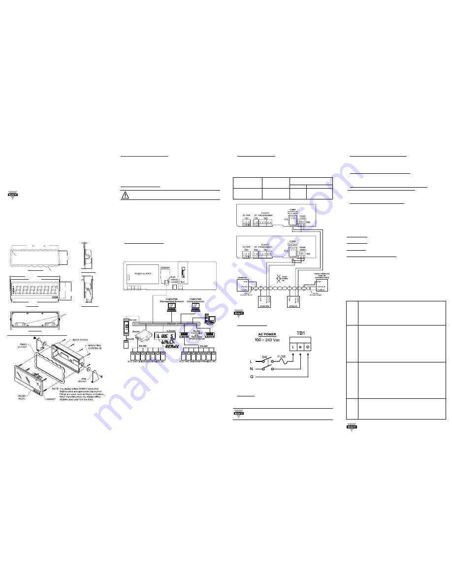
2. Wiring RS-485 Interface.
The RS-485 standard (multipoint) allows a computer, one or more
devices and Big Displays (up to 32) to be connected using a two-
wire connection (half-duplex) plus a common wire to connect to the
shield of the cable. It is recommended to use shielded cable with
one twisted pair for EMI noise protection.
Connections to the computer are optional.
3. Power Connection.
Connect the main power connections as shown in the figure below.
OPERATIONS
1. Peak Value
(Display in Host Mode)
Press
b
to request “Peak” value:
RS-485 Mode, will send:
*01X02 (Interface DRNT), or *01X03 (Interface DRNP)
In the examples for RS-485 it is assumed that the
device address is 01.
POWER
Computer Card
Device with
Remote Display
or Converter Box
RS-485 Pin
Pin Function
Function
RJ-12
Screw Terminal
A, -Tx/-Rx
-Tx/-Rx
4
3
B, +Tx/+Rx
+Tx/+Rx
3
2
COM
COM
1


