8
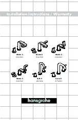
Installation
To help ensure the pump will start as required, check the pump regularly with start-up tests.
POWER SUPPLY
1.
The pump is equipped with a shock-proof plug according to regulations. The pump is designed to be
connected to 120 VAC, 60 Hz GFCI protected socket.
2.
Make sure that the socket is sufficiently secured and is in excellent condition.
3.
WARNING: To prevent death from electric shock, pump must be connected only to a GFCI protected outlet.
WARNING! If the power cord or plug is damaged, do not use the pump. The power cord or plug may only
be repaired by a certified electrician.
AREAS OF USE
•
This pump is designed to pump water only.
• This pump is designed to be used for: General purpose removal or transfer of clear water.
• This pump should NOT be used for: Continuous run, fountain/pond water features. Removing water from
swimming pools or spas. Septic or sewage systems.
• This pump can also be used to transfer water (e.g. household, farming, plumbing).
INSTALLATION INSTRUCTIONS
1. Attach hose to Pump intake port. Attach second hose to Pump discharge port.
2. Position Pump on solid surface so that both hoses are free from kinks.
3. Place unused end of intake hose in water to be transferred. Place unused end of discharge hose as
needed to direct the water discharge at least 3 feet away from the source.
INSTALLING THE WATER HEATER
MOUNTING-DRYWALL (HOLLOW WALL)
1. The selected wall or cabinet must be capable of supporting double the weight of the unit when completely
full of water (77 lbs).
2.
The installation area must provide adequate clearances for removal of the front panel and servicing the
unit.
3. Locate the wall studs in the area where the unit Is to be mounted.
4.
Cut two sections of 1/2 inch plywood or equivalent material 3 inches In height. The length of each section
should be sufficient to span the width of the wall studs.
5. Use appropriately sized nails or wood screws to attach the two wall supports to the wall.
6.
Drill two 13/32 inch holes in the upper wall support.
NOTE: The holes must be level.
7. Insert the hollow wall anchors into the drilled holes. Place the wall bracket over the anchors and screw the
two Phillips head screws down tight against the bracket.
MOUNTING-MASONRY WALL (SOLID WALL)
1. The selected wall or cabinet must be capable of supporting double the weight of the unit when completely