FM Transmitter
Sistemas Electrónicos S.A EM 250 COMPACT DIG
Technical Manual - v1.1 - February 2006
9
1.3 Front panel.
The EM-250 COMPACT DIG Front Panel is very clean and easy to control.The wide alphanumeric
display and the control keyboard allows a simple self-explanatory menu-driven navigation through the
various options. A great care was taken in the design of the software to allow natural feeling with the
controls to allow operation and programming in every respect of the Equipment without needing to
extensively read this manual.
The password management hides some functions and prevents tampering with the most critical
options and data to unauthorized people.
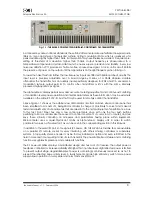
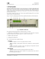
Figure 1-2 shows the simple Equipment's Front Panel, indicating all supervision and control elements:
Fig. 1-2: TRANSMITTER CONTROL PANEL.
These supervision andcontrol elements are numbered in Figure 1-2 as follows:
1
- ON/STBY switch. This ON/STANDBY key do not power off equipment, which is still locked on frequency
and ready to transmit as soon the key is pushed or a remote command is sent.
2
- STANDBY condition indicator LED.
3
- Cooling system's air intake slots.
4
&
7
- Alarm LEDs panel and operation LEDs panel:
ALARM PANEL
:
•
Alarm
red LED lights on in event of any equipment's alarm condition.
•
VSWR
red LED lights on showing that RF output circuit is overloaded by a severe high VSWR
condition.
•
Limiter
red LED lights on showing too high audio signal level at equipment's input,and
subsequent operation of baseband peak clipper.
OPERATION PANEL
:
•
Remote
amber LED shows remote-controlled operation is being carried on.
•
Lock
green LED shows when Channel Oscillator's PLL is properly locked, some tenths of
second after equipment is turned on.

