


10-004209-01EN [Q7750159], Rev. 2, May 2018
System Components
191
Figure 4
‑
131 Zip to close
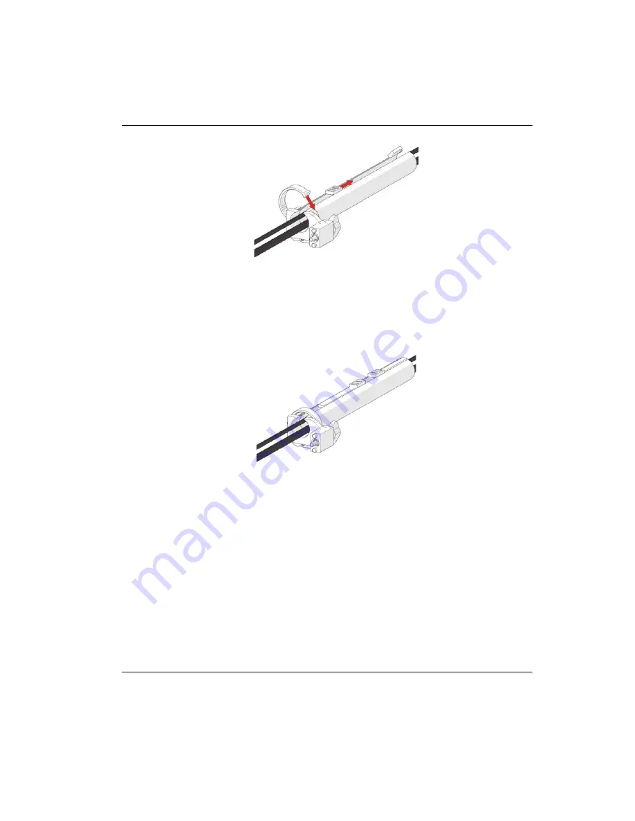
3.
After the cable is placed in the entire length of tube, bring the zipper from the
opposite end to meet at any point in the middle (see Figure 4-132 on page 191).
Figure 4
‑
132 Zip opposite end
When necessary, the two zippers may be opened to allow any cables to be routed out
of the tube (see Figure 4-133 on page 192).
Summary of Contents for SteerROVER
Page 8: ...10 004209 01EN Q7750159 Rev 2 May 2018 Table of Contents viii...
Page 10: ...10 004209 01EN Q7750159 Rev 2 May 2018 List of Abbreviations x...
Page 18: ...10 004209 01EN Q7750159 Rev 2 May 2018 Labels and Symbols 8...
Page 38: ...10 004209 01EN Q7750159 Rev 2 May 2018 Introduction 28...
Page 52: ...10 004209 01EN Q7750159 Rev 2 May 2018 Chapter 1 42...
Page 66: ...10 004209 01EN Q7750159 Rev 2 May 2018 Chapter 2 56...
Page 208: ...10 004209 01EN Q7750159 Rev 2 May 2018 Chapter 4 198...
Page 212: ...10 004209 01EN Q7750159 Rev 2 May 2018 Chapter 5 202...
Page 222: ...10 004209 01EN Q7750159 Rev 2 May 2018 Chapter 6 212...
Page 224: ...10 004209 01EN Q7750159 Rev 2 May 2018 Chapter 7 214...


