background image

– 2 –

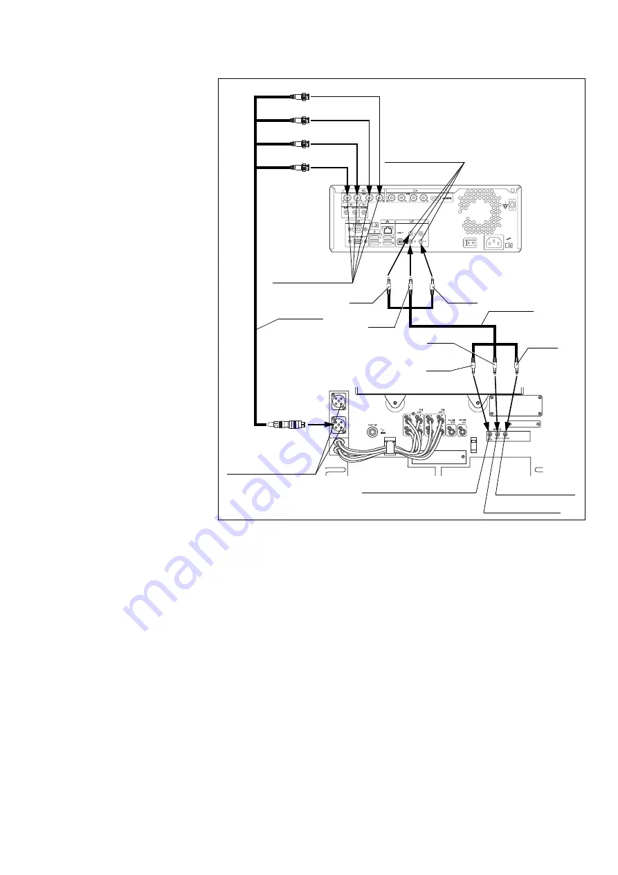
1.4 Connection of the video recorder

Connection of HVO-4000ST

OME-V200

HVO-4000ST

MAJ-2310

A (Red)

B (Green)

C (Blue)

D (White)

Playback terminal

Release terminal

Recording control terminal

SDI input 
terminals A to D

3G-SDI quad-link 
combined output 
1 or 2 terminal

REMOTE contact 
switch connectors

MAJ-2309

Red

Blue

Green

Green

Blue

Red

Summary of Contents for ORBEYE OME-V200

Page 1: ...e and confirm that this instrument is locked to the floor 1 2 Connection of the power cord Connect the power plug of the power cord directly into the hospital grade wall mains outlet Connection of LMD...

Page 2: ...ME V200 HVO 4000ST MAJ 2310 A Red B Green C Blue D White Playback terminal Release terminal Recording control terminal SDI input terminals A to D 3G SDI quad link combined output 1 or 2 terminal REMOT...

Page 3: ...w is visible do not use this instrument and contact Olympus 1 Confirm that this instrument and the ancillary equipment to be used are turned OFF 2 Confirm that the electrical contacts of the connector...

Page 4: ...light is output from the illumination lens of the microscope section Operate the observation monitor by following its instruction manual and confirm that it can display images 1 Using a white object...

Page 5: ...8 Observe your hand and confirm that the image is displayed in normal colors without noise 1 Tilt the scope switches A and B on the microscope section all the way upward or downward and by observing...

Page 6: ...nger from the scope switch C and confirm that the arm is locked and the microscope section can be fixed at the current position 4 If the arm free of the adaptive AF is set confirm that the auto focus...

Page 7: ...ection and rotate the microscope section around rotation axis A shown in a by 180 toward the front in the direction of arrow 1 to the positioning shown in b Then rotate the microscope section around r...

Page 8: ...grip sheet around the grip section of the microscope section and hold down the slack of the drape Peel off the release paper at the end of the grip sheet and firmly press the attaching bezel and attac...

Page 9: ...is not smooth or when the switch is unintentionally pushed by the drape If it still does not resolve please remove the strap and repeat from Step 11 13 Check that there is no breakage or adhesion of f...

Page 10: ...Loading the user preset 1 Tap the Load user preset button 2 Tap the user ID button to be set 3 The selected setting will appear on the user ID window on the touch panel Load user preset User ID User I...

Page 11: ...come heavy 1 Flip open the switch cover of this instrument and press the view field movement stop switch to stop the joystick operation 2 Press the scope switch C and move the microscope section Press...

Page 12: ...atient 2 Open the loupes storage section of the base and take out the loupes case 3 Take the loupes out of the loupes case 4 While pulling the loupes lock ring in the direction of the arrow insert the...

Page 13: ...e off the microscope section 6 Turn the loupes lock ring clockwise to secure the loupes on the microscope section Confirm that the caution line yellow is invisible 7 Hold the loupes adjust the width t...

Page 14: ...n of the observation monitor Inspection of the image Inspection of the focus zoom functions Inspection of the motorized field movement Inspection of the arm locking unlocking After inspection Store an...

Reviews: