6
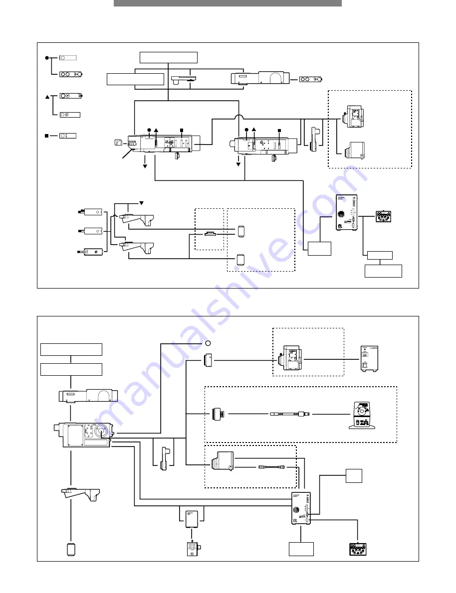
SYSTEM DIAGRAM
MOTORIZED UNIT SYSTEM DIAGRAM
BXFM-A SYSTEM DIAGRAM
See manual
U-D5BDREMC
U-D6REMC
U-FWO
BX-RFAA
U-AN360RAF
U-AFA1M
BX-RLAA
U-LH100-3
U-LH100L-3
U-FWR
Intermediate tubes
(Refer to pages 31-32)
Observation tubes
(Refer to pages 29-30)
U-DICRHC
U-DICR
U-DICRH
U-AN360-3
U-25ND6,
U-25ND25
U-25LBD
U-25IF550
U-25L42
U-25FR
U-PO3
U-AN
U-HSTR2
BX-UCB*
U-ZPCB
Z board
U-POTP3
PC
BX2BSW
Control software
Mirror units
U-LH75XEAPO
U-LH100HGAPO
U-LH100HG
BF/DF objective lenses
BF objective lenses
BD-M-AD
Refer to pages 38-40
Refer to page 26
Refer to pages 7-18
Refer to
page 35
* BX-REMCB is also available for BX-RLAA + motorized revolving nosepiece control (refer to page 39)
See manual
U-D6REMC
U-P5REMC
U-D5BDREMC
U-AFA1M
U-LH100-3
U-LH100L-3
U-LH100HG
U-LH75XEAPO
U-FWR
U-HSTR2
BX-UCB
Objective lenses
BXFMA-F
U-IFFH
U-FH
PC
U-RMT
ø32filter
Auxiliary lens
(provided with the BXFMA-F)
Power source
Video system
(Refer to pages 37-38)
Refer to page 41
Observation tubes
(Refer to pages 29-30)
U-ZPCB
Z board
U-LGAD
LG-PS2
LG-SF
Refer to page 26
Refer to pages 26-27
Refer to pages 27-28


