background image

IX71/IX51

CONTENTS

5

6-11

12, 13

14-31

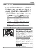
IMPORTANT  

— Be sure to read this section for safe use of the equipment. —

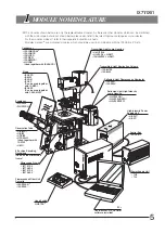
1     MODULE NOMENCLATURE

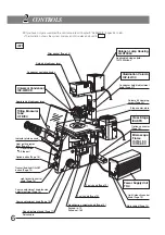
2     CONTROLS

3

4     USING THE CONTROLS

TRANSMITTED LIGHT BRIGHTFIELD OBSERVATION PROCEDURE

4-1  Power Supply Unit and Microscope Frame

.........................................................................................  

14-16

4-2  Focusing Block

.............................................................................................................................................................................  

16, 17


1

   Turning Power On, Adjusting the Brightness

2

   Light Path Selection


3

   Magnification Change (IX71 Only)

4

   Frame Clamping Plate


5

   Option Button (IX71 Only)

4-3  Stage

...........................................................................................................................................................................................................  

18, 19

4-4  Observation Tube

....................................................................................................................................................................  

20-22

4-5  Illumination Column IX2-ILL100

...........................................................................................................................  

22-24


1

   Tilting the Illumination Column

2

   Mounting the Filters


3

   Using the Field Iris Diaphragm

  4

   Adjusting the Condenser Height Adjustment Knob Tension


1

   Adjusting the Interpupillary Distance

2

   Adjusting the Diopter


3

   Using the Eye Shades

4

   Using Eyepiece Micrometer Disks


5

   Selecting the Light Path of Observation Tube (U-TR30H-2 Only)


6

   Using the CT Turret (U-BI90CT Only)

7

   Adjusting the Tilt (U-TBI90 Only)


1

   Rotation Direction of the Coarse/Fine Adjustment Knobs


2

   Adjusting the Coarse Adjustment Knob Tension


3

   Detaching the Fine Adjustment Knob

4

   Pre-focusing Lever

1-4


1

   Placing the Specimen

2

   Moving the Specimen


3

   Connecting the Grounding Wire

4

   Adjusting the X-Axis/Y-Axis Knob Rotation Tension

4-7  Condenser

..........................................................................................................................................................................................  

27-29


1

   Centering the Condenser

2

   Using the Aperture Iris Diaphragm


3

   Flipping Up the Condenser Holder

4-8  Objectives

..........................................................................................................................................................................................  

30, 31


1

   Oil-Proof Cap (UIS Series only)

2

   Adjusting the Correction Collar


3

   Using Immersion Objectives

Correct assembly and adjustments are critical for the microscope to exhibit its full performance. If you are going to
assemble the microscope yourself, please read Chapter 9, “ASSEMBLY” (pages 55 to 65) carefully. For the modules
provided with instruction manuals, also read the assembly procedures in their instruction manuals.

4-6  Illumination Column IX2-ILL30

.............................................................................................................................  

25, 26


1

   Using the Aperture Iris Diaphragm

2

   Removing the Condenser Lens


3

   Mounting the Filters

4

   Using the Filters

  5

   Mounting the Manipulator

Summary of Contents for IX71

Page 1: ...erted Microscopes Models IX71 and IX51 To ensure the safety obtain optimum performance and to familiarize yourself fully with the use of the microscope we recommend that you study this manual thorough...

Page 2: ......

Page 3: ...t U BI90CT Only 7 Adjusting the Tilt U TBI90 Only 1 Rotation Direction of the Coarse Fine Adjustment Knobs 2 Adjusting the Coarse Adjustment Knob Tension 3 Detaching the Fine Adjustment Knob 4 Pre foc...

Page 4: ...CC Rules These limits are designed to provide reasonable protection against harmful interference when the equipment is operated in a commercial environment This equipment generates uses and can radiat...

Page 5: ...pply and Hand Switch IX2 Software for PC CD ROM IX2 BSW Ver 01 03 or later Methods of PC control of microscope functions Precautions When Unpacking the Microscope Releasing the Transport Lock of the R...

Page 6: ...any consequence of user modification including introduction of the use of laser beam 5 The surfaces of the lamp housing will become extremely hot during operation When installing the microscope make s...

Page 7: ...EPA2 eye point adjuster With the combination of U TR30H U FWO the full optical performance may not be able to be manifested with the objectives listed in below and it is not possible to use the objec...

Page 8: ...ally available absolute alcohol Since the absolute alcohol is highly flammable it must be handled carefully Be sure to keep it away from open flames or potential sources of electrical sparks for examp...

Page 9: ...with IX MVR IX2 KSP Can be used together with CK40 MVR Eyepieces WHN10X WHN10X H Observation Tube U BI90CT U BI90 U TBI90 U TR30H 2 Used together with IX ATU U MO 6 Position Revolving Nosepiece Fixed...

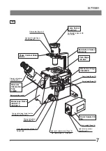
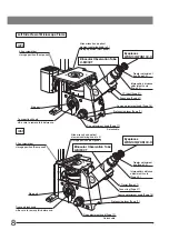
Page 10: ...nt knob tension adjustment ring Page 16 IX71 Filter pocket Page 23 Field iris diaphragm lever Condenser centering knobs Aperture iris diaphragm lever Indicator plate pockets Option button Page 16 Ligh...

Page 11: ...nt knob Page 17 Detachable Phase Contrast Slider IX2 SL Applicable halogen bulb 6V30WHAL Lamp Socket U LS30 3 Y axis knob Page 19 X axis knob Page 19 Light intensity control knob Page 14 Main switch P...

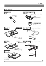
Page 12: ...adjustment knob Page 17 Detachable Pre focusing lever Page 17 Eyepieces WHN10X WHN10X H Binocular Observation Tube U BI90CT Allen wrench and optical element centering knob x 2 storage position Rear pa...

Page 13: ...rew holes CK40 MVR CK2 SS mounting screw holes Plain Stage IX2 SP IX MVR CK2 SS mounting screw holes On both sides Manipulator mounting screw holes M6 screws x 6 Cross Stage IX SVL2 Y axis knob Can be...

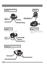
Page 14: ...entering knob insertion hole UCD Adapter IX ADUCD Condenser height fine adjustment knob Page 28 This is a manually controlled condenser Refer to the separate instruction manual for details Motorized L...

Page 15: ...ontrol knob POWER LED REMOTE LED Hand Switch TH4 HS The IX71 does not need this module because its functions are incorporated in the microscope frame Light intensity control knob Lamp ON OFF switch Po...

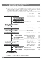
Page 16: ...with the light path selector lever Light path selector lever P 15 Place the specimen on the stage X axis and Y axis knobs P 19 Engage a 10X objective in the light path Revolving nosepiece Bring the s...

Page 17: ...IX71 IX51 With the IX71 Power Supply Unit TH4 Hand Switch TH4 HS With the IX51 When the TL4 power supply unit is used Make a photocopy of the observation procedure pages and post it near your microsco...

Page 18: ...identical function With the TL4 the position marked is not provided and even the maximum light intensity 6 V may sometimes be unsuitable for photomicrography With the IX71 Frame Fig 6 If the TH4 conne...

Page 19: ...0 light path with the IX71S1F 2 IX51S1F 2 frame Side port light path 80 Observation 20 light path with the IX71S8F 2 IX51S8F 2 The light path to the lower back port can also be set by the manufacturer...

Page 20: ...nt in the direction of the arrow raises the objective and toward the rear opposite direction lowers the objective Always use the rotation tension adjustment ring to control the rotation tension of the...

Page 21: ...proximate focus with the coarse adjustment knob turn the pre focusing lever in the direction of the arrow to lock it Hereafter the upper limit of the coarse adjustment will be limited at the position...

Page 22: ...ki plates 72 well or 60 well When using this it is necessary to replace the stage scales with those provided with the plate holder Petri dish holder is available for 35 mm 54 mm and 65 mm diameter pet...

Page 23: ...ge travel area is 130 mm X axis x 85 mm Y axis with the IX MVR or 120 mm X axis x 78 mm Y axis with the CK40 MVR 3 Connecting the Grounding Wire Fig 18 With the IX2 SFR or IX SVL2 Stage A grounding wi...

Page 24: ...d of view is clearly visible Fig 21 The diopter can also be adjusted using the eyepiece micrometer disks 2 While looking through the right eyepiece rotate the coarse fine adjustment knobs to bring the...

Page 25: ...aged in the light path and the objective exit pupil can be observed Used when centering the ring slit in phase contrast ob servation or adjusting the aperture iris diaphragm S Shield plate is engaged...

Page 26: ...an be created by tilting the illumination column Even with the illumination column tilted the specimen surface will be illuminated which is convenient for rough confirmation of the specimen location o...

Page 27: ...31 2 While holding the mounting lever of the filter holder insert a filter Fig 30 Hold the filter by its edge to avoid leaving fingerprints or smudges on the filter surfaces After the illumination has...

Page 28: ...g 34 2 Insert the Allen screwdriver into the hole on the condenser height adjustment knob and while holding the knob turn the screwdriver in the direction of the arrow to increase the rotation tension...

Page 29: ...ragm can be seen as shown in Fig 36 Its aperture can be adjusted by rotating the aperture iris diaphragm lever When the U BI90CT binocular tube is used the aperture iris diaphragm can be viewed by set...

Page 30: ...ickness of filters does not exceed 11 mm Using appropriate filters according to the purposes allows you to observe and photograph specimens more effectively Particularly the use of the 45LBD filter is...

Page 31: ...eld iris diaphragm image into focus 7 While gradually opening the field iris diaphragm rotate the condenser centering knobs on the condenser holder to adjust so that the field iris diaphragm image is...

Page 32: ...into focus 7 Using the field iris diaphragm lever stop down the field iris diaphragm until its image is just inside the field of view 8 Slowly slide the condenser height fine adjustment knob toward th...

Page 33: ...When using the U BI90CT binocular observation tube the aperture iris diaphragm can be observed by setting the turret to position CT or using the U CT30 centering telescope 3 Flipping Up the Condenser...

Page 34: ...cap Objective Series 3 Remark Oil proof cap Objective Series 3 Remark C1 UPlanFl100XO3 100XO3Ph 100XO3P Provided with microscope frame C1 1 piece C2 2 pieces C1 UApo20X3 340 40X3 340 40XOI3 340 20XW3...

Page 35: ...objective 3 Remove the specimen and move the stage insert cut out close to the objective front lens Apply a drop of the provided immersion oil to the objective front lens Place the specimen and rotate...

Page 36: ...IX PH2 small Ph2 UPlanFl40XPh LCPlanFl40XPh LCPlanFl60XPh UPlanApo20XPh LCAch40XPh LUCPlanFl40XPh SLCPlanFl40XPh IX PH3 large Ph3 UPlanFl100XO3Ph UPlanApo40XOI3Ph UPlanApo100XOI3Ph PlanApo60XO3Ph Inse...

Page 37: ...ttaching the Phase Contrast Optical Elements With the IX ULWCD Condenser Note The IX PHCU or IX PH1U can be attached only in the Ph1 or PhC position Do not remove the built in elements With the U UCD8...

Page 38: ...ted Do not tighten the optical element centering knobs too much for this may deform the frames of the optical elements 6 Place the index provided with each optical element in the index inser tion hole...

Page 39: ...rked so that the ring slit image overlaps with the phase plate of the objective A ghost of the ring slit image may be observed In this case overlap the brightest image with the phase plate If a thick...

Page 40: ...insert it in the idle position so that the surface with indication faces upwards 2 When attaching the IX2 SLPHC or IX2 SLPH1 optical element in the center position insert the provided centering knobs...

Page 41: ...is used to focus on the ring slit and the phase plate of the objective Figs 56 57 5 Using the optical element centering knobs turn the two centering screws of the phase contrast slider so that the rin...

Page 42: ...e in the 38 mm position 5 3 Differential Interference Contrast Observation Using the IX2 ILL100 Column DIC Slider Applicable Objective U DICT U DICTS Shift Type U DICTHC High Contrast Type U DICTHR Hi...

Page 43: ...IX DP40HC IX DP40HR 40XOI3 IX DPAO40 IX DPO40S 60X 100XOI3 IX DPO100 IX DPO100 PlanApo 60XO3 IX DPO60S UPlanApo 10XW3 IX DP10 IX DP10 60XW3 IX DPO60 IX DPO60 60XWPSF IX DPO60S IX DPO60S 60XW3 IR UApo...

Page 44: ...he index of the U ANT analyzer and the positioning groove of the U DICT DIC slider and drop the analyzer into the analyzer mount of the DIC slider Fig 60 3 Hold the U DICT so that the side with indica...

Page 45: ...When the U BI90CT binocular observation tube is used rotate the CT turret to position CT to engage the CT lens in the light path Fig 65 When the U BI90 U TBI90 binocular observation tube or U TR30H 2...

Page 46: ...n sensitive color observation using the U UCD8 engage the U UCDTP530 1 plate sensitive color plate in the light path Setting the background color to dark enables an observation like darkfield observat...

Page 47: ...bjective to be used to the revolving nosepiece and rotate it to engage the objective in the light path 4 Slide the polarizer rotation clamping knob on the polarizer unit horizontally in the counterclo...

Page 48: ...red index on the IX SPT straight photo tube then fit the circular dovetail of the straight photo tube into the photo port of the trinocular observation tube 3 Tighten the clamping screw firmly When th...

Page 49: ...90CT and U BI90 binocular observation tubes The finder eyepieces show four photo masks The numbers given to the masks correspond to the magnifications of the photo eyepiece Fig 72 1 Adjust the diopter...

Page 50: ...points Reduce light intensity for observation as low as possible Use additional heat barrier filters for observation For time lapse photography synchronize the on off of the light bulb with the exposu...

Page 51: ...instruction manual for the TV adapter to be used 2 Attaching the Camera on the Trinocular Observation Tube H Fig 74 Compatibility with various mounts from different manufacturers can be obtained by at...

Page 52: ...he Bottom TV Port IX2 TVR A C mount video camera used together with the U FMT or F mount video camera used together with the U FMT can be used by ordering the manufacturer to install and adjust the IX...

Page 53: ...e revolving nose piece clicks properly into place Light path selector knob is set for the side port light path Set the knob to the binocular eyepiece light path position or increase the light intensit...

Page 54: ...e glares Condenser is raised too high Lower to the proper position Aperture iris diaphragm is stopped down too far Open the aperture iris diaphragm f Visibility of observed image is poor Image is not...

Page 55: ...inning but see the overall field of view It is sometimes recommended to turn your eyes away from the eyepieces look far off and look into the eyepieces again i The coarse fine adjustment knobs will no...

Page 56: ...ce possible Eye point switchable in 2 steps of 400 and 430 mm U TBI90 Binocular tube with 35 to 85 tilting angle Diopter adjustment on one eyepiece possible Eye point 406 to 471 mm U TR30H 2 Trinocula...

Page 57: ...NA 1 3 WD 0 2 mm with correction collar UPlanFLN60X NA 0 9 WD 0 2 mm UPlanFLN60XOI NA 1 25 0 65 WD 0 12 mm with iris diaphragm UPlanFLN100XO2 NA 1 3 WD 0 2 mm UPlanFLN100XOI2 NA 1 3 0 6 WD 0 2 mm wit...

Page 58: ...ecifications UIS Series For phase contrast observation SLCPlanFl40XPh NA 0 55 WD 7 7 mm ring slit IX PH2 with correction collar For DIC and brightfield observation SLCPlanFl40X NA 0 55 WD 7 7 mm with...

Page 59: ...e instruction manuals Illumination column IX2 ILL100 High intensity light source U LH100HG U LH100HGAPO U LH75XEAPO Critical illumination lens IX CI Illumination column IX2 ILL30 Power supply unit TL4...

Page 60: ...90 in the direction of the arrow 4 While pushing down the bulb clamping lever down hold the halogen bulb with gloves or a piece of gauze insert the bulb pins straight and fully into the pin sections o...

Page 61: ...r Bulb Replacement During or Right After Use The bulb lamp socket and areas near these will be extremely hot during and right after use Set the main switch to OFF disconnect the power cord from the wa...

Page 62: ...Screw the IX SCL stage clips into the threaded holes provided on the stage top surface Fig 85 The IX2 SFR stage can be mounted by reversing the front and rear to implement a stage with knobs on the r...

Page 63: ...haped notch on the positioning bracket Fig 89 2 Using the Allen screwdriver tighten the clamping screw of the bracket lightly to the stage Fig 89 3 Align the stage s center alignment index line with t...

Page 64: ...rd and is more exposed to contamination than the objectives of upright microscopes Therefore if there are empty positions in the nosepiece attach the dust caps provided Fig 91 6 Figs 92 93 1 Loosen th...

Page 65: ...t position Fig 95 2 Loosen the condenser clamping knob Fig 95 3 Insert the mount of the UCD adapter into the mount dovetail of the condenser holder the condenser turret should be positioned on the rig...

Page 66: ...detached turned 180 and then attached on the observation tube mount again This lowers the eye point height by approximately 30 mm Fig 97 U TR30H 2 Tube Figs 98 99 First mount the IX ATU intermediate t...

Page 67: ...n on the right in the figure Using the Accessory Mounting Holes Fig 101 Twelve threaded holes are provided on the microscope frame for mount ing accessories such as a micromanipulator These holes are...

Page 68: ...provided by Olympus If no power cord is provided please select the proper power cord by referring to the section PROPER SELECTION OF THE POWER SUPPLY CORD at the end of this instruction manual 3 Conn...

Page 69: ...e the rear plate but uses the stabilizing feet clamping holes 1 Tilt the microscope frame slightly and insert the four rubber foot seats into the rubber foot sections This will disable the cushions of...

Page 70: ...nt by referring to Specifications and Certified Cord below CAUTION In case you use a non approved power supply cord for Olympus products Olympus can no longer warrant the electrical safety of the equi...

Page 71: ...Service for Cables BASEC BASEC HAR 10 10 30 N V KEMA KEMA KEUR HAR 10 30 30 SEMKO AB Svenska Elektriska Materielkontrollanstalten SEMKO HAR 10 10 50 sterreichischer Verband f r Elektrotechnik VE VE HA...

Page 72: ...time has exceeded 20 000 hours 2 Lamp does not light sometimes even though the main switch is set to on Except discharge burners 1 3 Illumination flickers when you move the lamp cable or lamp housing...

Page 73: ...MEMO...

Page 74: ...MEMO...

Page 75: ......

Page 76: ...ny 3500 Corporate Parkway P O Box 610 Center Valley PA 18034 0610 U S A One Corporate Drive Orangeburg NY 10962 U S A 491B River Valley Road 12 01 04 Valley Point Office Tower Singapore 248373 31 Gilb...

Reviews: