8
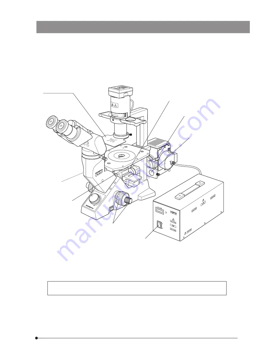
REFLECTED FLUORESCENCE SYSTEM
FOR CKX41
Excitation lightprotective shield
}Make a photocopy of the observation procedure pages on separate sheets and post it near
your microscope.
1
2
3
4
6
7
5
Page 1: ...e safety obtain optimum performance and to familiarize yourself fully with the use of this system we recommend that you study this manual thoroughly before operating the system Retain this instruction manual in an easily accessible place near the work desk for future reference Modules described in this manual CKX RFA U LH50HG U RFLT50 CKX NU This publication is printed on 100 recycled paper ...
Page 2: ......
Page 3: ...vation 4 Turning On the Mercury Burner 6 Centering the Field Iris Diaphragm 3 Applicable Fluorescence Objectives 5 Centering the Mercury Burner 1 3 9 17 21 28 20 5 TROUBLESHOOTING GUIDE 18 19 7 Switching the Filter Slider 2 CONTROLS OF EACH MODULE 3 SUMMARY OF REFLECTED FLUORESCENCE OBSERVATION PROCEDURE 4 USING THE CONTROLS 4 5 6 7 8 6 SPECIFICATIONS 7 ASSEMBLY 8 U EXCITATION FILTER SET CKX NU OP...
Page 4: ...d from the outlet connector on the power supply unit and wait 10 minutes or more until the lamp housing cools down 7 Do not open the lamp housing while it is turned on or for at least 10 minutes after it has been turned off Lamp housing parts are extremely hot and cause burns if touched see page 13 8 Do not remove the lamp housing while the burner is lit Also do not turn the burner on while the la...
Page 5: ...ed when handling and using the system Always heed the warnings Warning indication position 1 Getting Ready Lamp housing U LH50HG Warning against high temperature 1 The system is composed of precision instruments Handle it with care and avoid subjecting it to sudden or severe impact 2 Do not use the system where it is subjected to direct sunlight high temperature and humidity dust or vibrations For...
Page 6: ...he power supply unit indicates 100 hours replace the burner with a new one see page 26 Using a burner after its service life expires could lead to the burner exploding though this occurs very rarely 3 The surfaces of the dichroic mirror and excitation barrier filters are very delicate When it becomes necessary to clean it please contact Olympus 4 Do not disassemble any part of the system as this c...
Page 7: ...2ND6 12 25 50 Fluorescent objectives See pages 11 12 Microscope CKX41 Reflected fluorescent mirror slider B excitation G excitation Option U excitation filter set CKX NU Power Supply Unit U RFLT50 100 U RFLT50 200 A metal halide lamp can be used instead of the 50 W mercury burner except in U excitation Lamp housing U LH50MH Power supply unit U PS50MH The 100 W mercury burner cannot be used ...
Page 8: ...nterclockwise Field iris diaphragm centering screws Turn using the provided Allen wrench Filter slider Shutter Open position Filter pocket Dust covers x 2 With two clamping knobs View of light path indicators from the front side of microscope ND Filter 32ND6 12 25 50 Light Path G excitation B excitation Brightfield View No indication Lamp Housing U LH50HG Collector focusing knob Burner left right ...
Page 9: ...FLT50 The depth dimensions of the 100 V and 200 V models differ from each other Reset button Hour counter Main switch ON OFF Starter reset switch Frequency switch Voltage switch Burner type switch Fuse holders Power cord connector Lamp housing connector For exclusive use with the U LH50HG ...
Page 10: ...ible by stopping down the aperture iris diaphragm or transmitted phase contrast observation to facilitate it After locating the observation target position turn off the transmitted light illumination Controls Used Page Preparation Mount the objective suitable for the microscopy to be used Centering the mercury burner P 11 12 P 14 15 Set the main switch to ON and wait until the arc stabilizes 5 to ...
Page 11: ...8 REFLECTED FLUORESCENCE SYSTEM FOR CKX41 Excitation light protective shield Make a photocopy of the observation procedure pages on separate sheets and post it near your microscope 1 2 3 4 6 7 5 ...
Page 12: ...op in resolution due to variance in the cover glass thickness For details refer to the instruction manual for the CKX series culture microscopes 7 When it is required to interrupt observation for a short period use the shutter Repeated on off of the mercury burner will shorten its service life considerably 8 Precautions on the specimen color fading The system employs high intensity excitation ligh...
Page 13: ...er Fluorescent mirror specifications Excitation Fluorescent Mirror Dichroic Mirror Excitation Filter Barrier Filter Applications B DM500 BP460 490C BA520 IF FITC Fluorescent antibody method Acidine orange DNA RNA Auramine Tubercle bacillus EGFP S65T RSGFP G DM570 BP480 550C BA590 Rhodamine TRITC Fluorescent anti body method Propidium iodide DNA RFP U CKX NU DM400 BP360 370 BA420 Auto fluorescence ...
Page 14: ...trast IX2 SL IX2 SLP Excitation B G Specimen Plastic petri dish Plastic petri dish Multi well Dish etc Dish etc Applicable objectives UPlanFLN 4XPh UPlanFLN 4XPhP CAchN 10XPhP LCAchN 20XPhP LCAchN 40XPhP CPlanN 10XPh PlanN 10XPh LCAchN 20XPh LUCPlanFLN 20XPh LCAchN 40XPh Note When a phase contrast objective is used in fluorescence observation the brightness or contrast may sometimes be deteriorate...
Page 15: ...X2 SL IX2 SLP Excitation B G Specimen Plastic petri dish Plastic petri dish Multi well Dish etc Dish etc Applicable objectives UPlanFl 4XPh UPlanFl 4XPhP CAch 10XPhP LCAch 20XPhP LCAch 40XPhP CPlan 10XPh Plan 10XPh LCAch 20XPh LCPlanFl 20XPh LCAch 40XPh LCAch 40XPh 2 Note When a phase contrast objective is used in fluorescence observation the brightness or contrast may sometimes be deteriorated sl...
Page 16: ...s after ignition Use the shutter instead After the burner is turned off it cannot be re ignited before the mercury vapor cools and condenses to liquid Wait about 10 minutes before restarting the burner If the lamp housing is opened while the burner is ignited the safety interlock will activate and switch off the power automatically In this case set the main switch to OFF and wait for more than 10 ...
Page 17: ...1 to engage the B excitation mirror in the center position in the light path 3 Turn the field iris diaphragm lever 2 clockwise to open the iris diaphragm 4 Place a piece of white paper such as copy paper on the top of the stage set the filter slider 3 to the center position and project the arc image The arc image can be confirmed more easily by using the U CST centering target screen If the arc im...
Page 18: ...d mirror up down centering screw a to form the mirror reflected arc image on the white paper Figs 4 6 B 8 Adjust the mirror centering screws 9 and a to move the direct and mirror reflected arc images in the symmetrical position between each other and turn the mirror focusing screw b to adjust the size of the mirror reflected image until it is identical to that of the direct image Figs 4 6 C 9 Turn...
Page 19: ...image of the diaphragm to the center 5 After moving the diaphragm image to the center open the field iris diaphragm As this makes slight deviation notice able adjust the centering precisely 6 After completion of centering engage the iris diaphragm diameter until it just circumscribes the field of view Adjusting the field iris diaphragm The field iris diaphragm adjusts the diameter of the illumi na...
Page 20: ...oes not hinder operation 1 Slide the filter slider 1 on the illuminator in the direction of the arrow 2 Drop in the ND filter 3 into the filter pocket 2 To prevent the ND filter from being cracked insert it so that the surface with indications faces the observation side When replacing the ND filter be sure to wait until the ND filter cools down When the mercury burner is lit for a long period whil...
Page 21: ...on collar cannot obtain the required fluorescence perfor mance Use the objective with correc tion collar and adjust it to find the best position The objective or filter is dirty Clean them thoroughly The field iris diaphragm is adjusted improperly Adjust it so that it circumscribes the field of view c The edge of the field of view is obscured or not evenly illuminated The objective is improperly e...
Page 22: ...epeated ON OFF is possible in this case c The mercury burner flickers or the brightness is low The auto ignition safety mecha nism is activated Press the switch inside the starter reset hole on the right panel of the power supply unit and then set the main switch to ON again This phenomenon is observed in a short period after ignition Wait for 10 minutes or more after ignition The power supply vol...
Page 23: ...plicable high pressure mercury burners HBO50W AC OSRAM CS50W4 PHILIPS Power Supply Unit U RFLT50 100 U RFLT50 200 Ignition system Auto ignition Hour counter Displays the accumulated hours of operation Input rating Input voltage switchable U RFLT50 100 100 110 120 V AC 2 5 2 3 2 0 A 50 60 Hz U RFLT50 200 220 230 240 V AC 1 7 A 50 60 Hz Dimensions U RFLT50 100 150 W x 150 H x 320 D mm U RFLT50 200 1...
Page 24: ...embling the microscope system make sure that all parts are free of dust and dirt and avoid scratching any parts or touching the glass surfaces Dust cover Fluorescent mirror slider Microscope CKX41 Excitation light protective shield Reflected Fluorescence Illuminator CKX RFA Dust cover Dummy cover Lamp Housing U LH50HG Mercury burner Power cord Power Supply Unit U RFLT50 100 U RFLT50 200 ...
Page 25: ...the cover 1 Removing the Dummy Cover Fig 10 2 Figs 11 12 Removing the Dust Cover and Fluorescent Mirror Slider 1 Using the Allen wrench provided with the illuminator loosen the clamping knob 2 of the dust cover 1 and remove it 2 Using the Allen wrench provided with the illuminator loosen the stopper screw 4 of the fluorescent mirror slider 3 at the extremity of the CKX RFA illuminator and remove t...
Page 26: ...r the lower screw hole when clamping the illuminator 4 Attaching the Fluorescent Mirror Slider Attach the fluorescent mirror slider removed in 2 above attach the washer and tighten the screw 5 Attaching the Dust Covers Fig 14 The dust covers on the left and right are identical 1 Align the mounting hole 2 of the dust cover 1 and the screw hole 3 of the holding side of the slider and lightly secure ...
Page 27: ...G Lamp Housing Fig 16 Insert the collector 1 of the lamp housing into the illuminator rotate the lamp housing so that its top panel 2 becomes horizontal then tighten the two clamping screws 3 on the illuminator using the Allen wrench As the lamp housing surface becomes very hot during operation ensure that there is ample free space around the lamp housing especially above and below If the lamp soc...
Page 28: ...he clamping screw 2 and attach the extremity without the UP marking of the mercury burner 4 so that it comes on the lower side Then loosen the clamping screw 3 and attach the extremity marked UP Do not attach the mercury burner upside down Other wise the light may become dim and the original perfor mance will not be achievable In addition the burner service life may also be shortened Contamination...
Page 29: ... the burner set the main switch to OFF unplug the power cord and wait until the burner lamp housing and its surroundings cool down completely 6 Press the reset button 6 on the front of the power supply unit to reset the hour counter display to 0 0 Fig 20 The unit of hour counter display is hour Replace the burner when the displayed time reaches 100 0 hours Note that the above mentioned life of a m...
Page 30: ...by Olympus If no power cord is provided please select the proper power cord by referring to the section PROPER SELECTION OF THE POWER SUPPLY CORD at the end of this instruction manual If the proper power cord is not used product safety performance cannot be warranted 2 Connect the power cord connector 5 to connector 6 firmly Fig 22 3 Connect the power cord plug 7 to a wall outlet 8 Fig 23 Be sure ...
Page 31: ... Remove each of the fuse holders 9 by turning it counter clockwise using a flat blade screwdriver and pulling out 2 Replace both fuses with new ones Always use the designated fuses Otherwise a fire hazard may result 9 Fig 24 Applicable fuses U RFTL50 100 T4A H 250V LITTELFUSE 215004 2 pieces U RFTL50 200 T2 5A H 250V LITTELFUSE 215025 2 pieces ...
Page 32: ...t Excitation filter Barrier filter Filter holders x 2 Indication stickers To be attached on the light path indicators Mirror holder Construction of the fluorescent mirror slider Filter holder Barrier filter Mirror holder Dichroic mirror BF light path shield plate Excitation filter All pieces can be placed and replaced using a precision screwdriver Removing the UV cut filter Fig 25 Loosen the holde...
Page 33: ...n appliance coupling Table 1 Certified Cord A power supply cord should be certified by one of the agencies listed in Table 1 or comprised of cordage marked with an agency marking per Table 1 or marked per Table 2 The fittings are to be marked with at least one of agencies listed in Table 1 In case you are unable to buy locally in your country the power supply cord which is approved by one of the a...
Page 34: ...s Authority of Ireland NSAI Norges Elektriske Materiellkontroll NEMKO Asociacion Electrotecnica Y Electronica Espanola AEE Hellenic Organization for Standardization ELOT Instituto Portages da Qualidade IPQ Schweizerischer Elektro Technischer Verein SEV Elektriska Inspektoratet CEBEC HAR VDE HAR USE HAR IEMMEQU HAR BASEC HAR KEMA KEUR HAR SEMKO HAR ÖVE HAR DEMKO HAR NSAI HAR NEMKO HAR UNED HAR ELOT...
Page 35: ......
Page 36: ...57 U S A 491B River Valley Road 12 01 04 Valley Point Office Tower Singapore 248373 2 8 Honduras Street London EC1Y OTX United Kingdom 31 Gilby Road Mt Waverley VIC 3149 Melbourne Australia 6100 Blue Lagoon Drive Suite 390 Miami FL 33126 2087 U S A This publication is printed on recycled paper Printed in Japan 2004 09 M 010 ...