Teardown, Cleaning, and Reassembly of the Miscellaneous Parts of the Olympus BH-2 Microscope Frames
Revision 1
Page 42 of 45
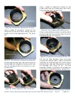
Place the knurled field-adjustment ring into position
over the frame of the Light Exit Assembly, with the edge
of the geared portion contacting the straight edge in
the cutout of the base casting (see
Figure 184
–
Place the knurled field ring into position
If the Light Exit Assembly is the all-plastic type (i.e., if
the knurled field-adjustment ring does not contain a
brass insert), apply a thin coating of a suitable light oil
(item 3 of
) to the bearing surface of the
plastic filter holder (see
Figure 185
–
Apply oil to the plastic filter holder
Place the filter holder into the center recess of the
knurled field-adjustment ring (see
Figure 186
–
Place the filter holder into recess of field ring
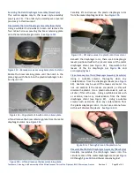
Rotate the filter holder until the three screw holes in
the filter holder align with the three tapped holes in the
frame of the Light Exit Assembly (see
Figure 187
–
Align holes in filter holder with tapped holes
While temporarily holding the filter holder in this
position, rotate the knurled field-adjustment ring and
observe its range of motion. It may not be possible to
adjust the ring such that the pointer goes from the dot
at the maximum clockwise end of travel to the dot at
the maximum counterclockwise end of travel (see
).
Figure 188
–
Field ring at maximum clockwise point
Figure 189
–
Field ring at maximum counterclockwise point


