
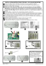


INSTALLATION INSTRUCTIONS FOR WALL OR CEILING MOUNTING
1
8
9
10
6
7
N
L
N
L
L1
L
N
L1
L
N
External
switch
Controlled operation of the lamp
Link
Permanent maintained operation
1
Remove the diffusor. Place a flat blade screwdrivers and pull up gently the reflector.
2
Install the included plastic cover in to the unused hole and install the base plastic (with the
included mounting screws and plugs).
3
Always use in any case round mains cable
,
with external diameter
of
6-9
mm (H05RN-F
type 2x1mm²
or
any
other type
,
at least
equal
to it’s mechanical and electrical properties).
ATTENTION!! The cable must not be deformed in any way (This requirement is important
to ensure the IP65 rating).
Install
the cable gland
,
pass the round cable through and tighten it all
the way.
4
Place the battery’s connector to the corresponding connector on the P.C.B
.
5
Connect the mains cables to the respective terminal block
(
connect the ground wire if required)
.
6
Ν
for neutral
,
L
for live wire
and
L1
for the maintained operation
.
The
L
1
wire can be connected
to an external switch to control the maintained or non maintained operation of the luminaire
.
7
For permanent maintained operation use two wires to power the luminaire,
Ν
for neutral and
L
for
live wire, and link the
L
and
L1
.
8
Install the
included tie (if needed) to fasten securely the power cables.
9
Refit the reflector and fasten the two small screws (included).
10
Finally place the diffusor by using the 4 included screws (tightening torque 1.2 Nm)
.
2
3
L1 L N
4
5
Page
3 from 4
923939100_09_013
Manual TEST or Resetting Errors
In order to test or reset the device
you must carefully remove the
diffusor by unfastening the 4
mounting screws. Then push the
button as described in the according
paragraphs on page 1 and 2.


