GR-750x series
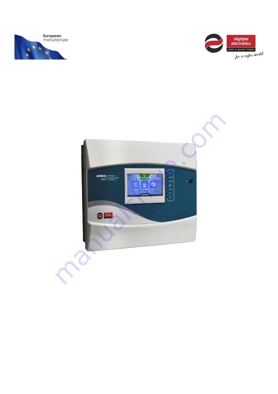
Control panels for addressable emergency luminaires
Quick installation guide
Page 1: ...GR 750x series Control panels for addressable emergency luminaires Quick installation guide...
Page 2: ...3 1 3 Terms and definitions 4 1 3 1 Point 4 1 3 2 Emergency mode In emergency 4 1 3 3 Inhibit mode 4 1 3 4 Loop circuits 4 1 3 5 Function test 4 1 3 6 Duration test 4 2 INSTALLATION 5 2 1 Mounting th...
Page 3: ...l network The maximum number of connected panels cannot exceed 24 The GR 750x series provides an ideal solution for medium to large scale facilities such as department stores hotels factories 1 2 Safe...
Page 4: ...dresses and a maximum of 250 points connected to it 1 3 5 Function test Function test procedure initiates a self test operational test procedure of the luminaires connected to the panel to verify thei...
Page 5: ...eries are connected Prior to any operation inside the enclosure of the panel ESD prevention measures should be taken The panel mounting area must be clean dry and free of collisions and vibrations The...
Page 6: ...l panel has space suitable for two 12V lead acid batteries Pb with nominal capacity of 7Ah 9Ah 12Ah or 15Ah Both batteries must be the same model type and have the same nominal capacity The two batter...
Page 7: ...on should be between 0 7mm2 and 2 5mm2 12 Low capacitance less than 200 pF m the total capacitance of a single cable should not exceed 400 nF Addressable Luminaire Connections 1 The GR 7500 can suppor...
Page 8: ...e Figure 5 Closed loop topology Table 1 Recommended cable cross section Loop cable length 200m 500m 1000m 1500m 2000m Point Number 50 0 75 mm2 1 mm2 1 mm2 1 5 mm2 2 5 mm2 100 1 mm2 1 mm2 1 5 mm2 1 5 m...
Page 9: ...se the address must be set using the panel by connecting and setting the luminaires one by one from the CHANGE POINT ADDRESS menu For more information on the point s address configuration refer to the...
Page 10: ...opology repeat the previous step for loop cable each L and its corresponding LF line and each shield line start finish 7 If points are not connected using a loop topology no return line connect tempor...
Page 11: ...ries in series and to the panel 7 Configure the date and time of the panel MAIN Technician Setting Time and date 8 Detect and register all connected points MAIN Technician Setup Find all points 9 Comp...
Page 12: ...board FAULT NIC Faulty NIC board Replace with another NIC board Datetime not set PANEL Date and time have not been set to the panel Set the date and time DATE TIME MENU Non group member PANEL NETWORK...
Page 13: ...Manually configure the specific luminaire to the correct model CONFIGURE POINTS menu Printer board comm PRINTER 1 Thermal printer card missing not connected 2 Faulty thermal printer card Check the pan...
Page 14: ...nent s wiring connections Power supply PRINTER PMU There is a problem with the power supply Check the power supply Check the cable connections If the problem persists replace the component Short circu...
Page 15: ...h the WEEE directive Electrical and electronic equipment should not be mixed with general waste Declaration of Conformity Olympia Electronics N Lakasas P Arvanitidis S A hereby declares that this prod...