background image

14

Installing the stove

The floor on which the stove is installed must be even and 

horizontal. The stove may only be installed on an adequate 

load-bearing floor. The stove can be stood on a  metal floor 

sheet or glass sheet to protect the flooring.

If the flooring or carpet is inflammable, a stable and non-

combustible spark protection plate must be used. This 

must extend 50 cm to the front and 30 cm to each side 

beyond the edge of the combustion chamber opening. 

Under the stove no spark protection plate is required.

Assembly sequence


If intended, install the OEC.


Install the side cladding.


The Ø150mm stovepipe connection can be installed at 

the top or rear. The stove is supplied ready for connec-

tion from above. If you wish to connect it at the rear, the 

following steps must be carried out to make the neces-

sary modifications:
-  Break out the cover in the back panel.
-  Replace the connector sleeve and the sealing cover. 


Decide where the stove is to be installed. There must be 

no objects made of combustible materials within a dis-

tance of 100 cm of the stove’s radiation area, measured 

from the combustion chamber’s inspection glass, nor 

may any be placed within this area subsequently.
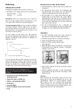
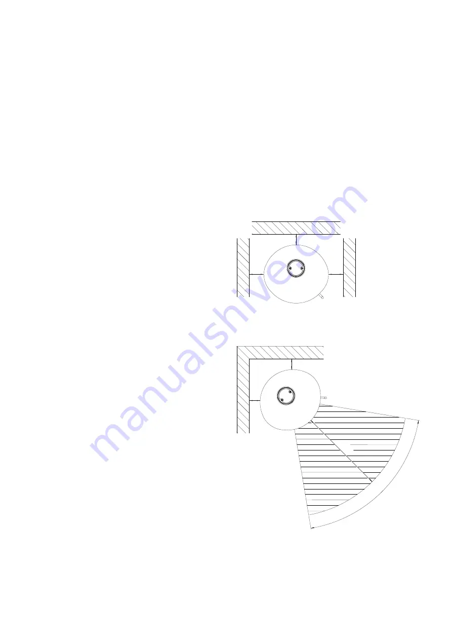
Depending on the installation position of the stove in 

front of walls that need to be protected (flammable or 

load-bearing), the following distances from walls need 

to be observed in accordance with the position of the 

combustion chamber door to the wall / side panel or 

the back panel (see schematic diagram).

When not dealing with walls that need to be protect-

ed, you merely need to observe a minimum distance of 

approx. 5 cm to allow for proper heat dissipation.


Install the pipe lining (provided on site) in the chimney. 

The connection height can be individually specified for 

a top stovepipe connection, however should not exceed 

1.5 m from the connector sleeve. For the rear stovepipe 

connection heights please refer the “Technical Data“ 

chapter. No combustible material is permitted within a 

radius of 20 cm around the stove pipe.


Connect the stovepipe at both connection points with 

stove putty so that the stove pipe is permanently sealed.


Push the stove onto its planned position and orient it so 

that the stovepipe fits into the pipe lining.

The stovepipe connections must be tight. The stove-

pipe must not protrude into the chimney.
Bear in mind that on partition walls in accordance with 

test specification EN 13240 the temperature of 85°C 

can be reached, and with light wallpaper or similar 

combustible construction materials this can result in 

colour changes.

37

37

25

Stove installed straight in corner

37

100

100°

37

Stove installed diagonally in corner

Dimensions in cm

Dimensions in cm

Summary of Contents for Tecapa II Compact

Page 1: ...apa II Compact 23 756 23 757 DIN EN 13240 DIN 18897 raumluftunabh ngig DIBt Bauaufsichtliche Zulassung 15a BV G GB D F NL Anleitung Seite 2 11 Instruction Page 12 19 Instructions Page 20 27 Aanwijzing...

Page 2: ...den sind umgehend innerhalb von 2Ta gen an Ihren Lieferanten zu melden Technische Daten Nennw rmeleistung 6 0 kW Raumw rmeleistung 6 5 kW Anschlussstutzen Ofenrohr 150 mm max Gewicht 225 kg Anschlusss...

Page 3: ...r am Stutzen 323 C Mindestf rderdruck bei Nennw rmeleistung 12 Pa Verbrennungsluftversorgung Der Kaminofen kann sowohl konventionell raumluft abh ngig als auch raumluftunabh ngig betrieben werden Es i...

Page 4: ...fen vor zu sch tzen den W nden brennbar oder tragend montiert wird sind entsprechend der Position der Feuerraumt r zur Aufstell bzw Seiten oder R ckwand folgende Wandabst nde einzuhalten siehe Prinzip...

Page 5: ...Stroh Beachten Sie vor dem ersten Heizen Alle Zubeh rteile aus dem Aschekasten und Feuerraum entnehmen Der auftretende Geruch durch das Verdampfen der Schutzlackierung verschwindet wenn der Kaminofen...

Page 6: ...tellen Dies gilt auch bei Schwachlastbetrieb Bei Nichtbetrieb den Bedienhebel auf 0 stellen um ein Ausk hlen des Aufstellraumes zu verhindern Feuerrost Bedienhebel f r den Feuerrost Mit dem Bedienhebe...

Page 7: ...ngsluftschieber ganz ffnen Nur kleine Menge Brennstoff auflegen Asche h ufig sch ren Verkleidung Die Verkleidungen d rfen nicht berheizt werden da sonst Risse auftreten k nnen Mit maximal 3 kg Holz he...

Page 8: ...rend des Heiz betriebes bei geschlosse ner T r gemessen werden kann Messstutzen Ersatzteile Achtung Eventuell ben tigte Ersatzteile fordern Sie bitte bei Ihrem Fachh ndler an Es d rfen ausschlie lich...

Page 9: ...nzug zu niedrig Ist das Brennholz nicht trocken der Kaminofen eine zu hohe Heizleistung abgibt Ist die Verbrennungsluftzufuhr zu weit offen Ist der F rderdruck zu hoch Sch den an der Rosteinrichtung a...

Page 10: ...geschriebene Betriebsspannung und bei Betrieb mit der angegebenen Energieart bzw mit den in der jeweiligen ger tespezifischen Aufstell und Bedienungsanleitung zugelassenen vorgeschriebenen Brennstoffe...

Page 11: ...aratur oder Lieferung ei ner mangelfreien Sache innerhalb eines angemessenen Zeitraumes durch uns oder einem von uns erm chtigten Fachbetrieb Der Sachmangel ist unverz glich sp testens jedoch inner ha...

Page 12: ...e of user comfort and high fuel utilisation en able it to be used as high quality space heating without having to do without the cosy atmosphere of an open fire Proper installation and correct handlin...

Page 13: ...ominal thermal output 12 Pa Combustion air supply The stove can be operated conventionally dependent on the ambient air as well as independent of the ambient air It must be guaranteed that there is en...

Page 14: ...n front of walls that need to be protected flammable or load bearing the following distances from walls need to be observed in accordance with the position of the combustion chamber door to the wall s...

Page 15: ...Straw Please note before heating for the first time Remove all accessories from the ash pan and combus tion chamber The odour given off by the evaporation of the protec tive coating disappears after t...

Page 16: ...ting lever should be set on I minimum This also applies in the event of low load operation When not operating the lever should be set on 0 to re duce the cooling down of the room Fire grate Operating...

Page 17: ...es sure can be disrupted What to do Open the combustion air slide valve complete Only put on a small quantity of fuel Frequently stoke the ash Cladding The cladding may not be overheated as cracks cou...

Page 18: ...he combustion chamber can be measured with the door closed during heating operation measuring duct Replacement parts Attention Please ask your specialist trader for any replacement parts required Alwa...

Page 19: ...draught too low Is the wood used as fuel not dry the stove gives off too much heat Is the combustion air supply open too wide Is the delivery pressure too high the grate becomes damaged or slags are f...

Page 20: ...it lev e du combustible permettent d employer ce four comme chauffage int rieur de qualit sans devoir renon cer l atmosph re douillet d un feu de chemin e L installation en bonne et due forme ainsi qu...

Page 21: ...oulement minimale puissance nominale 12 Pa Alimentation en air de combustion Le po le peut tre utilis aussi bien de mani re conven tionnelle en fonction de l air ambiant et qu ind pendam ment de l air...

Page 22: ...t selon la position de la porte du foyer de respecter les carts suivants avec le mur d installation le panneau la t ral ou arri re voir sch ma de principe Si le po le n est pas mont proximit de murs p...

Page 23: ...mage Paille respecter avant la premi re mise en service chauffer Sortir au pr alable tous les accessoires du cendrier et du foyer L odeur se produisant en raison de la vaporisation de la laque de prot...

Page 24: ...ande au minimum sur I durant la combustion Ceci est aussi valable en cas d exploitation charge r duite Lorsque l appareil est teint placer le levier de com mande sur 0 pour viter le refroidissement de...

Page 25: ...t N alimenter qu avec de petites quantit s de combustible Attiser souvent la cendre Habillage Il ne faut pas surchauffer l habillage car on pourrait vo quer des craquelures Pour chauffer utilisez 3 kg...

Page 26: ...ctionnement en laissant la porte ferm e Manchon de mesure Pi ces de rechange Attention Veuillez demander les pi ces de rechange dont vous au rez ventuellement besoin aupr s de votre commer ant sp cial...

Page 27: ...l trop faible Le bois n est il pas sec la charge du po le met elle un puissance thermique trop lev L alimentation en air de combustion est elle trop ouverte La pression de refoulement est elle trop le...

Page 28: ...oog brand stofverbruik maken de inzet als hoogwaardige ruimteverwarming mo gelijk zonder op de behaaglijke atmosfeer van een open haardvuur afstand te moeten doen Een opstelling volgens de voorschrift...

Page 29: ...atgastemperatuur op de aansluitstomp 323 C Minimum persdruk bij nominaal warmtevermogen 12 Pa Toevoer van verbrandingslucht De haardkachel kan op een conventionele manier afhan kelijk van de kamerluch...

Page 30: ...her men wanden brandbaar of dragend wordt gemon teerd moeten overeenkomstig de positie van de ver brandingsruimtedeur naar de opstel resp zij of ach terwand de volgende afstanden tot de wanden wor den...

Page 31: ...oor het eerste stoken Alle toebehoren uit de aslade en verbrandings ruimte verwijderen De optredende geur door het verdampen van de beschermingsverlakking verdwijnt wanneer de haard kachel meerdere ur...

Page 32: ...minstens op I staan Dit geldt ook tij dens lichte belasting Wanneer de haard niet in gebruik is moet de regelhen del op 0 staan om te vermijden dat de ruimte afkoelt Vuurrooster Regelhendel voor het v...

Page 33: ...randstof opleggen As dikwijls oppoken Bekleding De bekleding mag niet te heet worden omdat er anders scheuren kunnen ontstaan Met maximaal 3 kg hout verwarmen Aangezien de natuurstenen bekledingen van...

Page 34: ...derdruk in de brandruim te kan meten als de deur gesloten is en de haardkachel brandt Meetpunt Reservedelen Opgelet Eventueel benodigde reservedelen bestelt U alstublieft bij Uw vakhandelaar Er mogen...

Page 35: ...t brandhout niet droog het haardinzetstuk een te hoog verwarmingsvermo gen afgeeft Is de luchttoevoer te ver geopend Is de persdruk te hoog schade aan de roosterinrichting optreedt of zich slakken vor...

Page 36: ...1 78 4623 7561 05 2017 Olsberg GmbH H ttenstra e 38 59939 Olsberg T 49 2962 805 0 F 49 2962 805 180 info olsberg com olsberg com...

Reviews: