background image

JS-505

T

roubleshooting

Field Service Ver. 

1

.0 J

u

n. 2008

                                                                           6

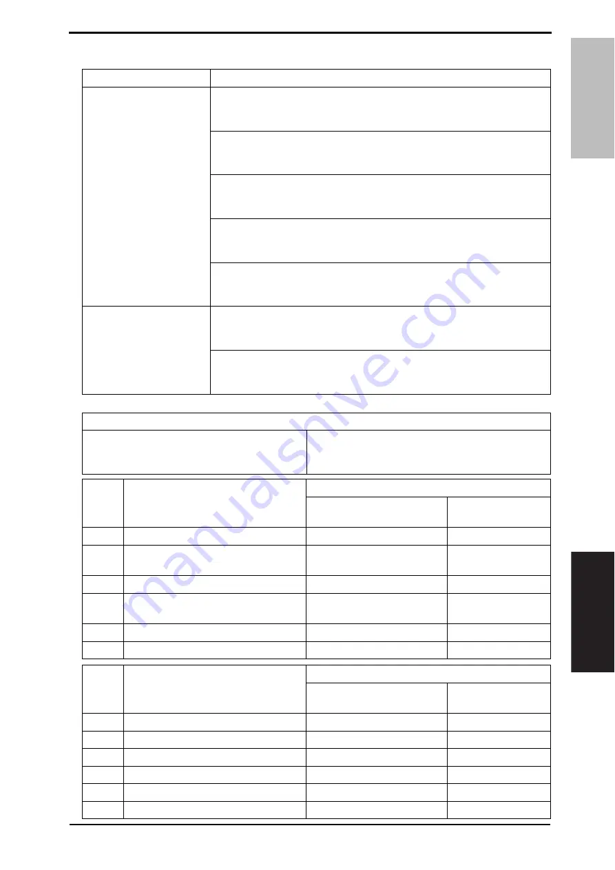
Jam display

A. Detection timing

Relevant electrical parts

Paper exit sensor (PS2)
Lower tray exit sensor (PS1)
Upper tray exit sensor (PS2)

JS control board (JSCB)
Printer control board (PRCB)

6

.3.

4

Job separator transport section misfeed

B. Action

WIRING DIAGRAM

Control signal

Location (Electrical 

components)

1

Initial checks

2

PS2 (paper exit sensor) I/O check, 
sensor check

3

PS1 I/O check, sensor check

JSCB PJ7-6 (ON)

JS-505 F-4 to 5

4

PS2 (Upper tray exit sensor) I/O check, 
sensor check

JSCB PJ7-9 (ON)

JS-505 F-4

5

JSCB replacement

6

PRCB replacement

Type

Description

Transport section misfeed 
detection

The lower tray exit sensor (PS1) is not turned ON even after the set period 
of time has elapsed after the copier’s paper exit sensor (PS2) is turned ON 
by the paper.

The upper tray exit sensor (PS2) is not turned ON even after the set period 
of time has elapsed after the copier’s paper exit sensor (PS2) is turned ON 
by the paper.

The lower tray exit sensor (PS1) is not turned OFF even after the set 
period of time has elapsed after the copier’s paper exit sensor (PS2) is 
turned OFF by the paper.

The upper tray exit sensor (PS2) is not turned OFF even after the set 
period of time has elapsed after the copier’s paper exit sensor (PS2) is 
turned OFF by the paper.

The paper exit sensor (PS25) is not turned ON even after the set period of 
time has elapsed after the copier’s paper exit sensor (PS2) is turned ON 
by the paper.

Detection of paper remain-
ing in the transport section

The lower tray exit sensor (PS1) is turned ON when the power switch is set 
to ON, a door or cover is opened and closed, or a misfeed or malfunction 
is reset.

The upper tray exit sensor (PS2) is turned ON when the power switch is 
set to ON, a door or cover is opened and closed, or a misfeed or malfunc-
tion is reset.

Ste

p

WIRING DIAGRAM

Control signal

Location (Electrical 

components)

1

Initial checks

2

PS25 I/O check, sensor check

3

PS1 I/O check, sensor check

JSCB PJ7-6 (ON)

JS-505 F-4 to 5

4

PS2 I/O check, sensor check

JSCB PJ7-9 (ON)

JS-505 F-4

5

JSCB replacement

6

PRCB replacement

d-Color MF201

d-Color MF201Plus - d-Color MF250 -

Ste

p

Action

Action

d-Color MF305

2

5

Y109081-8                                                      Sevice Manual

Summary of Contents for JS-505

Page 1: ...JS 505 Option Printer SERVICE MANUAL Code Y109081 8 d Color MF201 d Color MF201Plus MF250 MF350...

Page 2: ...PUBLICATION ISSUED BY Olivetti S p A 77 Via Jervis 10015 Ivrea TO Italy Copyright 2008 Olivetti All rights reserved...

Page 3: ...ft margin of the revised section The number inside represents the number of times the revision has been made To indicate clearly a page that contains the revision is shown near the page number of the...

Page 4: ...cification 1 Maintenance 2 Other 3 2 1 Disassembly adjustment prohibited items 3 2 2 Disassembly Assembly Cleaning list other parts 4 2 2 1 Disassembly Assembly parts list 4 2 2 2 Disassembly Assembly...

Page 5: ...1 23 6 3 3 Solution when paper curl occurs for d Color MF201Plus d Color MF250 MF350 24 5 3 4 Job separator transport section misfeed 25 7 Malfunction code 26 7 1 Trouble code 26 7 2 Solution 27 7 2 1...

Page 6: ...5 inch X 18 inch Min 148 mm X 210 mm 5 9 inch X 8 3 inch Plain paper 60 to 90 g m2 16 to 24 lb 50 sheets Lower tray A6S A5S A5 B6S B5S B5 A4S A4 B4 A3 A3 Wide 5 1 2 X 8 1 2S 5 1 2 X 8 1 2 8 1 2 X 11S...

Page 7: ...nge without notice Exit tray Lower tray Shift amount 30 mm Types of paper to be used Plain paper Thick paper 1 2 3 Size B5S B5 A4S A4 B4 A3 8 1 2 X 11S 8 1 2 X 11 8 1 2 X 14 11 X 17 Power require ment...

Page 8: ...o prevent them from being removed by mistake Do not remove or loosen any of the red painted screws in the field It should also be noted that when two or more screws are used for a single part only one...

Page 9: ...page 1 Unit Separator P 5 2 Exterior parts Front cover P 6 3 Rear left cover P 6 4 Rear right cover P 7 5 Upper tray P 7 6 Paper guide plate P 8 7 Board JS control board JSCB P 9 8 Motors Transport mo...

Page 10: ...achment plates 2 the attachment plate A with pieces of metal is required to be attached to the left Install the attachment plates as shown in the illustration Press them downward and secure them with...

Page 11: ...separator See P 5 2 Open the misfeed clearing cover 1 3 Remove two screws 1 and remove the front cover 2 2 3 3 Rear left cover 1 Remove the separator See P 5 2 Remove three screws 1 and remove the re...

Page 12: ...5 2 Remove the rear left cover See P 6 3 Remove three screws 1 and remove the rear right cover 2 2 3 5 Upper tray 1 Remove the separator See P 5 2 Remove the screw 1 Push two pro trusions 2 in the di...

Page 13: ...rator See P 5 2 Remove the upper tray See P 7 3 Remove two screws 1 and remove the paper guide plate cover 2 4 Remove eight paper guide plates 1 NOTE When reinstalling the paper guide plates 1 make su...

Page 14: ...ctors 1 from the JS control board 4 Remove four screws 1 and remove the JS control board 2 2 3 8 Transport motor M1 1 Remove the separator See P 5 2 Remove the rear left cover See P 6 3 Disconnect the...

Page 15: ...M3 1 Remove the separator See P 5 2 Remove the rear left cover See P 6 3 Remove the rear right cover See P 7 4 Remove the screw 1 and discon nect two connectors 2 and remove the route change motor as...

Page 16: ...otor See P 10 4 Remove the C clip 1 and the lever 2 and remove the route change guide 3 5 Remove two wire saddles 1 dis connect two connectors 2 and remove two screws 3 Pull out the sensor assy 4 in t...

Page 17: ...connector 1 remove two screws 2 and remove the harness from four wire saddles 3 Remove the sensor mounting plate assy 4 8 Remove three screws 1 and two shoulder screws 2 9 Remove two screws 1 A083F2C...

Page 18: ...crew 1 and remove the belt fixed plate 2 11 Remove five wire saddles 1 and pull out the shift drive section assy 2 in the direction of the arrow 12 Remove two screws 1 and remove the shift motor assy...

Page 19: ...le 2 and two screws 3 and remove the shift motor 4 2 3 11 Roller pressure retraction clutch CL1 1 Remove the route change motor See P 10 2 Remove the E ring 1 and discon nect the connector 2 and remov...

Page 20: ...2 4 1 Cleaning of the roller and roll A Periodically cleaning parts cycle Roller and roll Every 300 000 prints 1 Remove the separator See P 5 2 Using a cleaning pad dampened with alcohol wipe the rol...

Page 21: ...2 Other Field Service Ver 1 0 Jun 2008 16 JS 505 Maintenance Blank Page Service Manual Y109081 8...

Page 22: ...ght ventilation etc levelness of the installation site The original has a problem that may cause a defective image The density is properly selected The original glass slit glass or related part is dir...

Page 23: ...ual main body A083F3E504DA Service Manual Y109081 8 d Color MF201Plus d Color MF250 d Color MF350 Screen d Color MF201 Screen A083F3E501DA 4 1 Sensor check procedure A Procedure 1 Call the Service Mod...

Page 24: ...rt2 Upper tray exit sensor Paper present Paper not present T1FDTB LED Full Non sort1 Lower tray paper full detect board LED Full Other than full T2FDTB LED Full Non sort2 Upper tray paper full detect...

Page 25: ...Check 1 Call the Service Mode to the screen See P 338 of the main body service manual 2 Touch Finisher 3 Touch Job Separator 4 Touch Exit Motor Drive Route change Motor Drive Shift Motor Drive or Exi...

Page 26: ...Blinking and paper location Light ing are displayed on the touch panel of the main body 6 1 1 Misfeed display resetting procedure Open the corresponding door clear the sheet of paper misfed and close...

Page 27: ...isplay Field Service Ver 1 0 Jun 2008 22 JS 505 Troubleshooting 6 2 Sensor layout 1 Paper exit sensor PS2 2 Lower tray exit sensor PS1 3 Upper tray exit sensor PS2 A083F4C501DA 1 2 3 Service Manual Y1...

Page 28: ...3 Does paper curl occur under normal conditions under conditions other than those mentioned above YES Go to step 5 3 1 Call the Service Mode to the screen 2 Touch System Software Switch Setting 3 Touc...

Page 29: ...ange Warm Up Time 3 Change the setting to Mode3 See P 394 of the main body service manual OK NG Go to step 4 4 1 Call the Service Mode to the screen 2 Select System 1 Change Warm Up Time 3 Change the...

Page 30: ...or PS1 is not turned OFF even after the set period of time has elapsed after the copier s paper exit sensor PS2 is turned OFF by the paper The upper tray exit sensor PS2 is not turned OFF even after t...

Page 31: ...traction home sensor PS5 is not blocked after the set period of time has elapsed after the roller pres sure retraction clutch CL1 is turned ON start of a pressure operation The pressure retraction hom...

Page 32: ...g the compact flash card 3 Change JSCB Relevant electrical parts Shift motor M2 Shift home sensor PS6 JS control board JSCB Step Action WIRING DIAGRAM Control signal Location Electrical component 1 Ch...

Page 33: ...I O check sensor check JSCB PJ7 12 ON JS 505 F 4 4 CL1 operation check JSCB PJ6 4 ON JS 505 F 5 5 Change JSCB Relevant electrical parts Route change motor M3 Route change home sensor PS4 JS control bo...

Page 34: ...lor MF350 Relevant electrical parts JS control board JSCB Step Action WIRING DIAGRAM Control signal Location Electrical component 1 Disconnect and then connect the power cord Turn OFF the main power s...

Page 35: ...7 Malfunction code Field Service Ver 1 0 Jun 2008 30 JS 505 Troubleshooting Blank Page Service Manual Y109081 8...

Page 36: ...UPDATING STATUS DATE UPDATED PAGES PAGES CODE 09 2008 1ST EDITION 36 Y109081 8...

Reviews: