background image

Repair information

4-35

Image transfer unit (ITU)

1.

Write down the number on the new ITU before installing it. You will need the 16-digit numeric value from 
the barcode after the installation, and it is easier to see at this point.

2.

Remove the right cover. See 

“Right cover removal” on page 4-7

.

3.

Remove the rear shield. See 

“Rear shield removal” on page 4-7

4.

Remove the waste toner container. See 

“Waste toner bottle” on page 4-67

5.

Remove the imaging unit (IU). See 

“Imaging unit (IU) removal” on page 4-40

.

Note:  

The ITU FRU includes a spring clamp kit. If the printer does not have this kit installed, perform the 

following steps to prepare for the later installation. Continue below wit

“Removal of ITU without the 

spring clamp kit” on page 4-35

. If the spring clamp kit is not installed, skip to 

“Continuing the removal 

(with or without the spring clamp kit)” on page 4-37

.

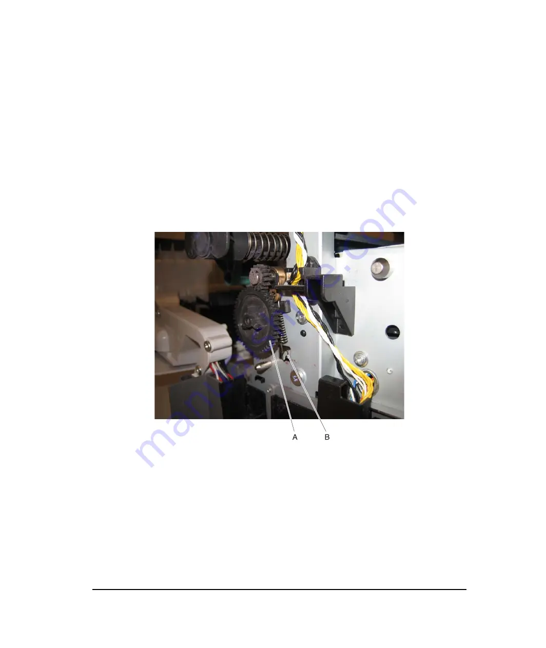
Removal of ITU without the spring clamp kit

1.

Pull the gear (A) straight out to un

snap

 it, and then discard it. A new gear is included in the spring clamp kit 

and must be used with the new spring clamp.

2.

Remove the rubber pad (C).

3.

Place the spring clamp onto the shaft (D).

Y112730-2

Summary of Contents for d-Color MF920

Page 1: ...SERVICE MANUAL Copiatrici Copiers d Color MF920 d Color MF923 Code Y112730 2...

Page 2: ...PUBLICATION ISSUED BY Olivetti S p A 77 Via Jervis 10015 Ivrea TO Italy Copyright 2010 Olivetti All rights reserved...

Page 3: ...specifications 1 11 Media output size and type 1 11 Media guidelines 1 13 Paper characteristics 1 13 Unacceptable paper 1 13 Selecting paper 1 14 Selecting preprinted forms and letterhead 1 14 Storin...

Page 4: ...2 39 Input sensor S2 service check 2 40 Main drive gear assembly EP drive service check 2 41 Operator panel service check 2 42 One or more operator panel buttons fail 2 42 Operator panel display blank...

Page 5: ...to second level support 2 76 User operator panel menus and messages 2 77 Understanding the operator panel 2 77 Operator panel buttons 2 77 2 78 Menu map 2 79 Diagnostic aids 3 1 Menu key combinations...

Page 6: ...tion Menu 3 31 Available tests 3 31 USB Scan to Local 3 31 Prt Quality Pages 3 31 Color Trapping 3 31 Reports 3 32 Menu Settings Page 3 32 Event Log 3 32 Panel Menus 3 32 PPDS Emulation 3 32 Demo Mode...

Page 7: ...transfer 3 62 Step 5 Fuse 3 63 Step 6 Clean Erase 3 64 Paper path transport components 3 66 Paper path Information 3 66 Transport components 3 67 Duplexing models with duplex support only 3 67 Scanne...

Page 8: ...lower frame 4 48 Main drive gear assembly with motor removal 4 53 Pick tires removal integrated 250 sheet media tray 4 55 Printhead removal 4 56 Imaging unit IU removal 4 57 Toner cartridge contacts...

Page 9: ...1 Front 5 1 Rear 5 2 Interior view 5 3 Printer boards 5 4 Controller Board 5 4 Connectors 5 5 HVPS 5 15 Connectors 5 16 LVPS 5 17 Connectors 5 18 Toner meter card 5 19 Toner meter card connectors 5 1...

Page 10: ...x Service Manual Y112730 2...

Page 11: ...dnungsgem er Wartung durch den Kundendienst Laserbestrahlung die Klasse I bersteigen w rde Menschen keinesfalls erreicht Avis relatif l utilisation de laser Pour les Etats Unis cette imprimante est ce...

Page 12: ...e 5 milliwatts operando numa faixa de comprimento de onda entre 770 e 795 nan metros O sistema e a impressora laser foram concebidos de forma a nunca existir qualquer possiblidade de acesso humano a r...

Page 13: ...let alttiina n kym tt m lle lasers teilylle l katso s teeseen VARNING Osynlig laserstr lning n r denna del r ppnad och sp rren r urkopplad Betrakta ej str len Laser notis Denna skrivare r i USA certif...

Page 14: ...Els productes l ser de classe I no es consideren perillosos Aquesta impressora cont un l ser de classe IIIb 3b d arseni r de gal li nominalment de 5 mil liwats i funciona a la regi de longitud d ona d...

Page 15: ...Notices and safety information xv Y112730 2...

Page 16: ...xvi Service Manual Y112730 2...

Page 17: ...Les consignes d entretien et de r paration de ce produit s adressent uniquement un personnel de maintenance qualifi Le d montage et l entretien de ce produit pouvant pr senter certains risques lectri...

Page 18: ...xviii Service Manual Y112730 2...

Page 19: ...el mantenimiento de este producto est dirigida exclusivamente al personal cualificado de mantenimiento Existe mayor riesgo de descarga el ctrica y de da os personales durante el desmontaje y la repara...

Page 20: ...orientada exclusivament a professionals i no est destinada a ning que no ho sigui El risc de xoc el ctric i de danys personals pot augmentar durant el proc s de desmuntatge i de servei d aquest produc...

Page 21: ...king printer adjustments and removing and installing FRUs 5 Connector locations uses illustrations to identify the connector locations and test points on the printer 6 Preventive maintenance contains...

Page 22: ...xxii Service Manual Y112730 2...

Page 23: ...with scan function The FAX function delivers a wide range of functionality to the office user The MFPs can be used as shared network or desktop devices Models The MF92x series MFPs are available in th...

Page 24: ...and 512MB Maximum printer memoryb 640MB Flash memory 64 MB Option Slots single slot is available or either font or flash memory card Font card support 1 font card Optional user flash memory card sizes...

Page 25: ...Menu Settings and press Select Replacement is recommended every 30 000 pages for the imaging unit 4800C Q default full printer speed 1200 dpi reduced printer speed is supported in PS and PCL only Con...

Page 26: ...is set to one minute Fuser standby is off The operator panel back light is off Power supply energy consumption is reduced Energy Paper All of the above Data streams MF920 MF923 PCL 6 emulation PostSc...

Page 27: ...5 7 in 21 kg 46 2 lbs MF923 422 mm 16 6 in 424 mm 16 7 in 416 mm 16 4 in 25 kg 54 9 lbs 550 sheet Duo Drawer 133 mm 5 2 in 424 mm 16 7 in 416 mm 16 4 in 4 kg 8 7 lb Description Clearances MF920 MF923...

Page 28: ...8 to 259 V ac extreme Notes Using a 220 V ac to 110 V ac power converter with a low voltage printer is not recommended Using an inverter to change DC to AC voltage 12 V to 120 V for example is not rec...

Page 29: ...ions Operating Air temperature operating 15 6 to 32 20 C 60 to 90 0 F Air temperature power off 10 0 to 43 30 C 50 to 110 0 F Air relative humidity Relative Humidity 8 to 80 Wet bulb temperature opera...

Page 30: ...f all inputs is 4 650 sheet Duo Drawera includes 100 sheet MP feeder 550 sheets or 100 sheets in MP feeder 550 sheets or 100 sheets in MP feeder Multipurpose try capacity 650 sheet Duo Drawer 100 shee...

Page 31: ...7mm A5a 148 x 210mm A6 JISb B5a 182 x 257mm Letter 8 5 x 11 in Legal 8 5 x 14 in Executivea 7 25 x 10 5 in Oficio Mexico Folio 8 5 x 13 in Statementa 5 5 x 8 5 in Universalc 148 x 210mm to 216 x 356mm...

Page 32: ...lower if A5 Statement B5 A6 Executive Statement Universal narrower than 210mm or envelopes are loaded b Japanese Industry Standard c Although the user may select Universal paper size for these sources...

Page 33: ...ledb Glossy Paper backed labels Bond Envelopes Rough envelopes Letterhead Preprinted Colored paper Light paper Heavy paper Rough or cotton Custom type x b a For MP feeder and manual feeders the Defaul...

Page 34: ...Laser printer 170 to 180 g m2 45 to 48 lb bond Labels upper limit Paper 131 g m2 35 lb bond Envelopes Multipurpose feeder or manual slot only Sulfite wood free or up to 100 cotton bond 60 to 105 g m2...

Page 35: ...rapper until it is time to use it This limits the exposure of paper to moisture changes that can degrade its performance Condition paper before printing by storing it in its original wrapper in the sa...

Page 36: ...ntact the paper supplier Preprinted papers such as letterhead must be able to withstand temperatures up to 200 C 392 F without melting or releasing hazardous emissions Storing paper Use these paper st...

Page 37: ...ower bending resistance than is required for reliable paper feeding Before using these types of paper for laser electrophotographic printing consult your paper supplier Remember that these are general...

Page 38: ...n 1200 dpi optical CDD 1200 dpi and 600 dpi Selectable through electronics Color depth 48 bit RGB output 16 bit channel Flatbed document specifications Document size Up to A4 and letter 4 5 x 5 5 to 8...

Page 39: ...Duplex scan Duplex and copy is available only on MF923 machines Scan file output formats TIFF JPEG PDF Supported compressions PDF 1 bit JBIG2 CCIT G4 Flate 8 24 bit Flate JPEG TIFF 1 bit CCITT G4 8 24...

Page 40: ...nteed North American and Europe PTT standard Input Level Range Ring Detection 16dBm 59dBm Complies with all regulatory requirements Receive 200x100 dpi 200x200 dpi 300x300 dpi 400x400 dpi 204x98 dpi 2...

Page 41: ...screwdriver magnetic 2 Phillips screwdriver magnetic 2 Phillips screwdriver magnetic short blade 7 32 inch 5 5 mm open end wrench 7 0 mm nut driver Needlenose pliers Diagonal side cutters Spring hook...

Page 42: ...byte character set dc Direct Current DIMM Dual Inline Memory Module DLE Downloadable emulator DRAM Dynamic random access memory DVM Digital multimeter ECC Error correcting code ECM Error correction m...

Page 43: ...ose feeder MR Modem ready MROM Masked Read Only Memory MS Microswitch NAND NAND usage NAND gate NVM Nonvolatile Memory NVRAM Nonvolatile Random Access Memory OCF Operator correctable failure OCR Oil c...

Page 44: ...edge feed SIMM Single Inline Memory Module SOL Solenoid SOS Start of scan SRAM Static random access memory TAR Toner Add Roll TPS Toner Patch Sensing TTM Tandem Tray Module TVOC Total Volatile Organi...

Page 45: ...symptom table on page 2 3 Scan fax copy symptom table on page 2 4 If you have an error message or user message check the following Service error messages on page 2 15 User status and attendance messa...

Page 46: ...ls appears 7 The operator panel display clears again 8 The operator panel displays system information For example 9 The fuser lamp turns on The fuser takes longer to warm up from a cold start than a w...

Page 47: ...each tray and adjust on the operator panel if necessary Unexpected page breaks occur Increase the Print Timeout value on the operator panel Settings General Settings Timeouts Print Timeout Multipurpos...

Page 48: ...mber but fails to make a connection with another fax machine The other fax machine may be turned off Ask the fax recipient to check their machine Incoming fax has blank spaces or poor quality 1 The se...

Page 49: ...icient fusing Go to Print quality insufficient fusing on page 2 53 Missing image at edge Go to Print quality missing image at edge on page 2 53 Mottle 2 5mm speckles Go to Print quality mottle 2 5mm s...

Page 50: ...ob The printer needs to pick media from the missing tray or the trays below it Tray x Tray 1 Tray 2 Tray 3 Note This message displays when refilling the trays during a job Before filling tray a tray t...

Page 51: ...an alternate source for media Cancel the current job Load single sheet size Printer does not detect media meeting the description size in the single sheet feeder manual feeder The following actions ca...

Page 52: ...Tray x Missing Insert the specified tray into the printer Unplug and Change Mode Camera is not in a proper mode to use the PictBridge feature Unplug the camera cable to the printer and change the came...

Page 53: ...the current job 35 RES Save Off Deficient Memory This message displays when the printer lacks sufficient memory to enable Resource Save This message usually indicates the user has allocated too much m...

Page 54: ...following actions can be taken press Select to clear the message and continue printing The job may not print correctly Simplify the print job press Menus to access the Busy Waiting Menu The following...

Page 55: ...layed the first time reporting of further errors is suppressed until the printer is reset or menus are entered The following actions can be taken press Select to clear the message Any data received on...

Page 56: ...The term color includes black cyan magenta and yellow Replace the toner cartridge and press Select to clear the message and continue printing 88 Replace color Cartridge The term color includes black...

Page 57: ...xx Paper Jam x Pages Jammed Multiple pages of media are jammed at the exit sensor Open the printer rear door to access the jam area Remove all the jammed pages See 202 paper jam on page 3 42 230 xx Pa...

Page 58: ...Paper Stop This message displays when paper is inserted past the paper stop on the ADF Remove original documents from the ADF 291 00 Scanner Jam remove all originals from the scanner Scanner ADF detec...

Page 59: ...ce check on page 2 57 106 11Service Yellow Printhead Failure writing data to printhead Perform a POR If the problem persists go to Printhead service check on page 2 57 106 12 Service Yellow Printhead...

Page 60: ...he problem persists go to Printhead service check on page 2 57 108 04 Service Magenta Printhead The magenta printhead mirror motors lost PLL motor lock Perform a POR If the problem persists go to Prin...

Page 61: ...Perform a POR If the problem persists go to Printhead service check on page 2 57 122 xx Service Fuser Error Fuser error Go to Fuser service check on page 2 39 122 01 Service Fuser Error EWC error Att...

Page 62: ...5 Service Staging Motor Staging motor has encountered a stall timeout Go to 90x xx error on page 2 31 150 xx Service Black ITU cartridge Motor Black ITU Cartridge Motor Go to Main drive gear assembly...

Page 63: ...ge 2 41 8xx service errors 840 01 Scanner disabled The scanner is disabled and can t be used Enter the configuration menu and re enable the scanner module Go to 840 xx service check on page 2 63 840 0...

Page 64: ...C card Excessive noise test for the dark data indicating some sort of CCD or analog electronics issue on that channel or channels Go to CCD service check on page 2 65 845 02 Cable SCC Failure Front sc...

Page 65: ...ave a modem installed even though its Configuration ID indicates that a modem should be present 848 01 Modem Config ID Mismatch A device has a modem installed but its Configuration ID indicates that a...

Page 66: ...not detect zero crossing Replace the LVPS See Low voltage power supply LVPS assembly on page 4 43 940 xxService Cyan TMC Sensor The cyan cartridge toner meter cycle TMC switch error 01 Recoverable 02...

Page 67: ...eck CRC check or the NAND experienced an uncorrectible multi bit failure loc indicates the source of the failure and has one of the following values CRC Failure The source is a failing package indicat...

Page 68: ...Replace controller board See Controller board removal on page 4 18 959 23 Service System Board System self test failure during initialization Replace controller board See Controller board removal on p...

Page 69: ...replace the network card If a network card is not installed replace the controller board 978 xx Service Standard Network or 978 xx Service Network Card x Bad checksum while programming network port C...

Page 70: ...uipment check condition has occurred in the specified device but the device is unable to identify the exact component failure Note device can be one of the following Duplex option Tray2 Tray 3 Service...

Page 71: ...reshold 7XX Error occurred when sending a frame Check line quality Adjust Transmit Level Select a lower Max Speed value under Fax Send settings 800 Received EOT unexpectedly from the modem in V34 mode...

Page 72: ...odulation scheme 813 Timeout occurred after waiting too long to receive a good frame Adjust Receive Threshold 814 Tried too many times at selected speed using V34 modulation scheme Adjust Transmit Lev...

Page 73: ...ully in V27 terminal modulation scheme Select a lower Max Speed under Fax Send settings Adjust the Transmit Level Check line quality 888 Failure to transmit training successfully at 2400 bps in V27 te...

Page 74: ...ction needed A01 Received request for unsupported image width from remote fax device No action needed A02 Received request for unsupported image resolution from remote fax device No action needed A03...

Page 75: ...emoval on page 4 18 Securely make all the connections POR the printer Step Questions actions Yes No 1 Turn off the printer and remove the rear shield See Rear shield removal on page 4 7 Unplug the fan...

Page 76: ...MIRR1 and JPH1 on the controller board Check for damage Are the cables damaged Replace the printhead See Printhead removal on page 4 56 Go to step 2 2 Turn the printer on and verify the following valu...

Page 77: ...nput S2 sensor is part of the autocompensator mechanism ACM and is not available separately Step Questions actions Yes No 1 Have any updates been made to the firmware Reload the firmware and try again...

Page 78: ...e sensor test See Base Sensor Test on page 3 18 Toggle the bin full flag attached to the rear shaft of the redrive unit Does the flag rotate freely and interrupt the sensor beam when in normal positio...

Page 79: ...s the JLVPS1 cable correctly connected at JLVPS1 on the controller board Go to step 5 Reconnect the JLVPS1 cable and go to step 4 4 Turn the printer off and then on Does the problem persist Go to step...

Page 80: ...e sensor Remove the obstruction and restart the test Go to step 4 4 Inspect the spring loaded shaft flag in the tray The flag portion of the shaft intercepts the sensor except when a sheet is being st...

Page 81: ...top cover assembly See Top cover assembly removal on page 4 9 Go to step 4 4 With the front cover open inspect the two switches Using a tool such as a spring hook push the metal arms to check the move...

Page 82: ...er in and out of the sensor Does the display indicate Media Clear and Media Present with the cycle Sensor is good Go to step 3 3 Does the flag rotate freely but returns to block the sensor Go to step...

Page 83: ...he cable for pinch points and the cable or connector for any other damage Is the cable damaged Repair or replace the LVPS cable See Low voltage power supply LVPS assembly on page 4 43 Go to step 4 4 C...

Page 84: ...front of the center autocompensator mechanism housing It should rotate freely and return to its original position Is the input S2 sensor flag damaged Replace the autocompensator mechanism See Autocomp...

Page 85: ...ged Replace the JCARTB1 cable Go to step 2 2 Disconnect the cable at JCARTB1 on the controller board and verify the following values Are the voltages correct Go to step 3 Replace the controller board...

Page 86: ...er emits five beeps and sticks in a continuous pattern until the printer is turned off Step Questions actions Yes No 1 Run the Button Test See Button Test on page 3 13 in Diagnostics Menu Did any of t...

Page 87: ...operator panel cable See Op panel cable on page 4 101 Step Questions actions Yes No 1 Turn off the printer and remove the rear shield See Rear shield removal on page 4 7 Disconnect the cable at JOPP1...

Page 88: ...98 Replace the operator panel cable See Op panel cable on page 4 101 Step Questions actions Yes No 1 Turn off the printer and remove the rear shield See Rear shield removal on page 4 7 Disconnect the...

Page 89: ...panel removal on page 4 98 Replace the operator panel cable See Op panel cable on page 4 101 Step Questions actions Yes No 1 Check the op panel USB cable for continuity Is there continuity Replace the...

Page 90: ...nd Faxes on the host computer Delete all print jobs in the print queue Is the printer online and in a Ready state Go to step 5 Go to step 4 4 Change the printer status to online Did this fix the issue...

Page 91: ...e wireless card is properly seated on the controller board Is the wireless card seated correctly Go to step 20 Go to step 19 19 Properly reseat the wireless card Did this fix the problem Problem resol...

Page 92: ...gs Toner Darkness Set to 4 default Color Saver Set to OFF RGB Brightness RGB Contrast RGB Saturation Set to 0 Color Balance Select Reset Defaults to zero out all colors Check the paper type texture an...

Page 93: ...Select the imaging unit you want to change and press Select 5 Select Yes and press Select If this does not fix the problem go to step 2 Go to step 2 2 Is the background only one of the primary colors...

Page 94: ...y if one specific color is a problem For example print the Print Quality Test Pages 1 Enter Diagnostic mode Turn the printer off press and hold Left and Select turn the printer on and then release the...

Page 95: ...set Did the motor run Go to step 5 Replace the Main drive gear assembly See Main drive gear assembly with motor removal on page 4 53 5 Remove the developer unit See Developer unit removal on page 4 42...

Page 96: ...ower supply HVPS assembly removal on page 4 31 Print quality half color page A photoconductor unit is not properly seated Reset the specific photoconductor unit Print quality horizontal banding Print...

Page 97: ...ning prints through and the problem normally clears up If the problem persists replace the developer cartridge Step Questions actions Yes No 1 Is the printer setup to use the correct media Go to step...

Page 98: ...See Developer unit removal on page 4 42 Step Questions actions Yes No 1 Is there any loose or foreign material on the imaging unit Inspect the imaging unit by looking at the individual developers and...

Page 99: ...distance from the original image to the same point on the residual image Is the distance 43 9 mm Replace the developer corresponding to the color of the image See Developer unit removal on page 4 42...

Page 100: ...en you replace the imaging unit This will block the laser from discharging the photoconductors Print a Quality Test Page Does the page have a white vertical band Replace the printhead See Printhead re...

Page 101: ...he controller board the printhead cable for pinch points and the cable or connector for any other damage Is the cable damaged Replace the printhead See Printhead removal on page 4 56 Go to step 2 2 Tu...

Page 102: ...Test on page 3 18 Does the operator panel display a change of state Replace the toner cartridge Replace the toner meter cycle TMC card See Toner meter cycle TMC card removal on page 4 61 Step Question...

Page 103: ...the problem Problem resolved Go to step 3 3 Turn the printer off and remove the rear shield See Rear shield removal on page 4 7 Turn the printer on and check the cable at JHVPS1 connector on the cont...

Page 104: ...t assembly is affected replace the entire 550 sheet assembly Contact the next level of support 4 Does the message Tray x Missing fail to appear when the tray is pulled out Go to step 5 Problem resolve...

Page 105: ...onnected to JOPT1 for continuity Is there continuity Go to step 8 Go to step 7 7 Replace the cable and print from both option trays Did the pages print from both trays Problem resolved go to step 8 8...

Page 106: ...onnect the cable at JOPT1 on the controller board Turn the printer on and measure the voltages below Are the voltages correct Consult your second level support Replace the controller board See Step Qu...

Page 107: ...1 on the controller board Are the connections properly connected Go to step 5 Go to step 4 4 Properly connect the connections on the ADF relay card and controller board POR the machine into configurat...

Page 108: ...perly connected Go to step 10 Go to step 9 9 Properly connect all the connections Did the 840 xx error recur Stop Problem solved Go to step 10 10 Replace the flatbed unit See Flatbed removal on page 4...

Page 109: ...d See Controller board removal on page 4 18 Step Questions actions Yes No 1 Restart the device and retry the scan copy job Repeat this step with a few copy jobs Does the error return Go to step 2 No i...

Page 110: ...le 4 Check pin 1 in JFBM1 for voltage The voltage is only present when a flatbed copy job is running The voltage should measure 24V AC Is voltage present Go to step 5 Replace the controller board Go t...

Page 111: ...ep 8 7 Clean the dirt and debris from the sensor Does this fix the issue Issue resolved Go to step 8 8 Inspect the connections on the ADF relay card in the ADF Are all the connections properly connect...

Page 112: ...e the sensors working properly Go to step 6 Go to step 9 6 Check the leading edge of the paper to ensure the paper is not curled or bent in a way that would keep it from contacting the paper present s...

Page 113: ...to step 5 There is no issue 5 Is the leading edge of the paper wrinkled or torn Use different media Go to step 6 6 Perform the ADF paper present sensor test Go to Scanner Tests on page 3 25 Is the sen...

Page 114: ...ADF relay card Are they properly connected Go to step 4 Properly connect all the connections 4 Check the ADF cable to ensure it is properly connected to CN 15 on the ADF relay card and main controlle...

Page 115: ...m resolved Go to step 5 5 Is the modem card ribbon cable properly connected to the system board at JMOD2 and the modem card Go to step 7 Go to step 6 6 Properly connect the modem card cable to the mod...

Page 116: ...tep 6 6 Is the line being used a VOIP line Go to step 7 Go to step 8 7 Have the system administrator verify that the VOIP server is configured to receive faxes Is the server properly configured Go to...

Page 117: ...el setting in steps of 1db For example if default value is 11 db changing it to 12db will decrease the signal strength by 1db and changing it to 10db will increase the signal strength by 1db Recommend...

Page 118: ...nable Fax Receive setting is on Is the setting set to on Go to step 9 Go to step 8 8 Set Enable Fax Receive to On Did this fix the problem Problem resolved Go to step 9 9 Is Distinctive Ring enabled G...

Page 119: ...decreasing increasing the Receive Threshold setting in steps of 2db For example if default value is 43 db changing it to 45db will decrease the received signal level by 2db and changing it to 41db wil...

Page 120: ...ted information This is where you will type in the information you retrieved in step 3 Second level support can assist you if you have questions about the information requested on the page Note The fi...

Page 121: ...lect press Select to initiate action on a menu item Navigation buttons press or to scroll through menu lists Indicator light Indicates the printer status Back Returns the display to the previous scree...

Page 122: ...the output Duplex press this to output a copy job with printing on both sides of the output sheet Address book press this key to enter the address book Fax mode setup Redial Pause press this to initi...

Page 123: ...ste Toner Bottle Reports Menu Settings Page Device Statistics Network Setup Page Shortcut List Fax Job Log Fax Call Log E mail Shortcuts Fax Shortcuts Profiles List Print Fonts Print Directory Print D...

Page 124: ...2 80 Service Manual Y112730 2...

Page 125: ...group contains the settings and operations used while manufacturing and servicing the printer Go to Diagnostics Menu Diag Menu on page 3 2 for more information Network SE Menu 1 Enter Customer Network...

Page 126: ...le tests on page 3 2 Bottom Margin Left Margin Right Margin Skew Quick Test ALIGNMENT Menu color alignment Cyan These testes are performed to align the color planes See Alignment on page 3 7 Yellow Ma...

Page 127: ...me See Model Name on page 3 19 Configuration ID See Configuration ID on page 3 19 ITU Barcode Enable Edge to Edge Copy See Enable Edge to Edge Copy on page 3 20 Reset Fuser Cnt EP SETUP EP Defaults Se...

Page 128: ...anner Tests ASIC Test See ASIC Test on page 3 25 Feed test See Feed Test on page 3 25 Sensor Test See Sensor Test on page 3 25 EXIT DIAGNOSTICS This selection exits Diagnostics mode and Resetting the...

Page 129: ...gnment This must be performed before color skew adjustment is attempted The following illustration shows proper alignment versus skewed alignment Right margin 50 to 50 Each increment corresponds to an...

Page 130: ...ormation including current page count installed memory serial number and code level To print the Quick Test page Note Print the Quick Test Page on letter or A4 paper 1 Select REGISTRATION from DIAGNOS...

Page 131: ...res that the best line in each set of lines must be selected To get started 1 Select Alignment Menu from the Diag Menu and press Select 2 Select a color Cyan Yellow or Magenta and press Select Note Th...

Page 132: ...lue for the Top Margin 6 Use or to enter the sum of the numbers and press Select Submitting changes appears Print the Quick Test again to verify the observed value is the same as the current value no...

Page 133: ...if the observed values and the current values are the same 8 On the second page of the latest Quick Test you printed proceed to Step 2 adjust the left right and bow settings Continue printing the Qui...

Page 134: ...elect MISC TESTS in the Diag Menu and press Select Remove Cartridge press Select appears 2 Select Motor Detect Note Do not press Select yet 3 Remove all toner cartridges and the imaging unit 4 Close t...

Page 135: ...3 Select Single or Continuous and press Select If Single is selected a single page is printed If Continuous is selected printing continues until Stop is pressed to cancel the test If a source is selec...

Page 136: ...rint quality pages from the Diagnostics Menu 1 Select PRINT TESTS and press Select 2 Select Print Quality Pgs and press Select The message Printing Quality Test Pages is displayed Note Once the test i...

Page 137: ...AM Test This test checks the validity of DRAM both standard and optional The test writes patterns of data to DRAM to verify that each bit in memory can be set and read correctly To run the DRAM Test 1...

Page 138: ...nter and the following screen is displayed c Upon completion of the POR the following screen is displayed P represents the number of times the CACHE Test has passed finished successfully Initially 000...

Page 139: ...e Quick Test Page from the default paper source Check the Quick Test Page for the correct offset between the placement of the first scan line on the front and back side of the duplexed sheet For infor...

Page 140: ...the front of the duplex page and the first scan line on the back of the page Therefore be sure to set the top margin in REGISTRATION before setting the duplex top margin See Registration on page 3 4...

Page 141: ...ingle or Continuous and press Select Single a single sheet of blank paper is fed and the test stops Continuous sheets are fed continuously until Stop is pressed Sensor Test This test is used to verify...

Page 142: ...st is unsuccessful Flash Test Failed appears Replace the flash card 4 press Back to remove the message and return to the Device Tests menu Sensor Value How to test Input Front Door Value opened Not cl...

Page 143: ...m DIAGNOSTICS and press Select 2 Select Serial number and press Select press Back to return to PRINTER SETUP Engine Setting 1 through 4 Warning Do not change these settings unless requested to do so b...

Page 144: ...uration ID 2 4 Repeat the steps for entering the Configuration ID 2 and press Select If the Configuration ID 2 is validated Submitting Selection appears and a check appears next to Printer Setup 5 Res...

Page 145: ...Select 3 Select Restore to reset the values to the factory settings and select Do Not Restore to exit without changing the settings To cancel and return to the menus press Back Fuser Temp This adjustm...

Page 146: ...ered If the number is incorrect Checksum does not match appears and the original screen appears to re enter the value If the number is correct Saving changes to NVRAM appears Reset Color Cal This sett...

Page 147: ...event log 1 Select EVENT LOG from Diag Menu and press Select 2 Select Display Log and press Select Up to three error codes display at a time press or to view additional error codes press to view addit...

Page 148: ...ss Select press Back to return to EVENT LOG Clear Log Use Clear Log to remove the current information in the Event Log This affects both the viewed log and the printed log information 1 Select Clear L...

Page 149: ...bed xxxx ADF xxxx is displayed press Return or Stop to clear the message Sensor Test A series of sensor tests are available to test the scanner s ADF and flatbed sensor functionality The following tab...

Page 150: ...owing steps 1 In the sensor test menu press or to scroll to the ADF paper present test 2 press Select Starting Test displays ADF Paper Closed displays 3 press the ADF paper present sensor actuator A t...

Page 151: ...nsor To test this sensor perform the following steps 1 In the sensor test menu press or to scroll to the Home sensor test 2 press Select 3 Starting Test displays 4 Home Closed displays 5 Home Open sho...

Page 152: ...ess Select Starting Test displays Sensor 1 Closed displays 3 Lift the ADF top cover and close the ADF cover sensor by pressing down on the ADF sensor actuator A with a small flat blade screwdriver 4 p...

Page 153: ...displays Sensor 2 Closed displays 3 Lift the ADF top cover and close the ADF cover sensor A by pressing down on the ADF sensor actuator with a small flat blade screwdriver 4 Move the Sensor 2 actuato...

Page 154: ...3 30 Service Manual EXIT Diags press Select to exit Diag Menu The printer performs a power on reset and returns to normal mode Y112730 2...

Page 155: ...ttings and printer and toner cartridge configuration information The remaining pages only contain graphics For samples of the pages see Print quality test pages Prt Quality Pgs on page 3 11 Configurat...

Page 156: ...menu settings 1 Select Reports from the Config Menu and press Select 2 Select Menu Settings Page and press Select Event Log Lets the system support person print a limited set of the information contai...

Page 157: ...ady prompt select Menus and press Select 3 Select Reports and press Select 4 Select Menu Settings Page and press Select 5 Enter the Diagnostic Menu select Reports Menu Settings Page and press Select S...

Page 158: ...does not occur When an event other than page count triggers this calibration the count that monitors the maximum number of pages printed will be reset For example if the user replaces an empty toner...

Page 159: ...gin values one pixel in the respective direction 9 Press to accept the value 10 Scroll to Top Edge and press 11 Use the or to increase or decrease the settings value Note pressing moves the margin up...

Page 160: ...atbed and press 7 Scroll toLeft Edge and press 8 Use the or to increase or decrease the settings value Note Each button press moves the margin values one pixel in the respective direction 9 Press to a...

Page 161: ...essing decreases the value and pressing increases the value 3 press to accept the setting Pel Blurring The Pel Blurring setting is used if step artifacts are noticed by the customer on copies and scan...

Page 162: ...On or off Code Revision Info Network Code Level Displays network code level Network Compile Info Displays compile information Printer Code Level Displays printer code information Printer Compile Info...

Page 163: ...cut or trimmed by hand Do not mix paper sizes weights or types in the same stack Store the paper in an appropriate environment Do not remove trays while the printer is printing Wait for Load tray x o...

Page 164: ...the fuser Open the front door and remove the jam 3 41 3 202 Jam in the fuser Open the front door and pull the fuser cover toward you Remove the jam 3 42 4 230 Jam in the duplex Open the front door and...

Page 165: ...ragments are removed 3 Insert the tray 4 press Select 201 paper jam 1 Grasp the front door at the side handholds and then pull it toward you to open it 2 Remove the jammed paper Note Make sure all pap...

Page 166: ...at the side handholds and then pull it toward you to open it 3 Grasp the green lever and pull the fuser cover toward you 4 Hold the fuser cover down and then remove the jammed paper The fuser cover c...

Page 167: ...r size 2 Insert the tray 3 Close the front door 4 press Select to continue printing 24x paper jam 1 Remove the 650 sheet Duo Drawer tray 2 out 2 Remove the jam Note Make sure all paper fragments are r...

Page 168: ...paper jam 1 Remove all original documents from the ADF input tray 2 Open the ADF top cover Remove the jammed paper 3 Close the ADF cover 4 Open the flatbed cover Remove any jammed pages 5 Close the sc...

Page 169: ...emove all original documents from the ADF input tray 2 Remove the ADF input tray See ADF input tray on page 4 84 3 Remove the original from the ADF by pulling the lower of the two sheets A from the AD...

Page 170: ...r port can be established on the host computer The virtual printer port is needed so the host computer can communicate with the printer Note Make sure the printer is attached over USB and Ready or Inv...

Page 171: ...rowse dialog displays 7 In the file browse dialog browse to the fullnet fls also called 1 fls file The fullnet fls file is the RIP firmware file Warning It is critical that the RIP firmware gets updat...

Page 172: ...d progress messages will appear on the printer s operator panel Warning Do not turn the machine off until the update is complete When the firmware update is completed the printer will automatically re...

Page 173: ...k the Browse Files button The file browse dialog displays 14 In the file browse dialog browse to the updeng fls also known as 2 fls file The fullnet fls file is the engine firmware file This is the se...

Page 174: ...atus and progress messages will appear on the printer s operator panel Warning Warning Do not turn the machine off until the update is complete When the firmware update is completed the printer will a...

Page 175: ...k the Browse Files button The file browse dialog displays 21 In the file browse dialog browse to the scanner fls also known as 3 fls file The scanner fls file is the scanner firmware file This is the...

Page 176: ...Click Start The printer will start the update process Various status and progress messages will appear on the printer s operator panel Warning Warning Do not turn the machine off until the update is c...

Page 177: ...ge the machine or render it inoperable 4 Press Select Program Device Yes displays 5 Press Select The printer will start the update process Various status and progress messages will display on the oper...

Page 178: ...fls must be the first file to be updated failure to update this file first could damage the machine or render it inoperable The printer will start the update process Various status and progress messag...

Page 179: ...Browse button A file browser will open 8 Browse to fullnet fls also known as 1 fls Warning fullnet fls must be updated first Failure to do so could render the printer inoperable 9 Click Open 10 Click...

Page 180: ...firmware page opens 25 Click the Browse button A file browser will open 26 Browse to scanner fls also known as 3 fls 27 Click Open 28 Click Submit Various status and progress messages will appear on...

Page 181: ...nsfer to the ITU and second transfer to the media 5 Fuse the toner to the media 6 Clean erase the photoconductor and the ITU In summary the printer s controller board receives print data and the comma...

Page 182: ...Service tips If the surface of the charge roller is damaged such as a nick or pit it will cause the charge to be uneven on the photoconductor This will cause a repeating mark on the printed page Check...

Page 183: ...inated with toner or other debris it will cause vertical streaking of white lightness on the page Cleaning the lens will solve the problem Never touch the surface of the photoconductor with your bare...

Page 184: ...ue to write on a can and then rolling it over glitter The glitter sticks to the glue but won t stick to the rest of the can Service tips Never touch the surface of the developer roller with your bare...

Page 185: ...contact between the Photoconductors and the ITU belt Service tips Never touch the surface of the ITU belt with your bare hand The oil from your skin will cause a charge differential on the surface an...

Page 186: ...age on the transfer belt reaches the transfer roll the negatively charged toner clings to the media and the entire image is transferred from the transfer belt to the media Service tips If the transfer...

Page 187: ...use toner to be pulled off the page or cause paper jams Toner that rubs off a printed page can be a sign of a malfunctioning fuser or an improper media setting Always check the paper type setting befo...

Page 188: ...e photoconductors Transfer Unit Clean Once the toner image on the transfer belt has been transferred to the page the transfer belt rotates around and is cleaned by the cleaning blade G This occurs for...

Page 189: ...he photoconductors a cleaning blade H scrapes the remaining toner from the surface of each photoconductor This is the clean erase process Now the photoconductor surface is prepared to begin the EP cyc...

Page 190: ...atches the user s settings It is not uncommon to find a user printing on cardstock with the printer programmed to print on a plain paper setting The printer s feed and transport components can fail an...

Page 191: ...models with duplex support only The MFPs with duplex support use a secondary paper path in the front cover and the 250 sheet paper tray to print on the second side of a sheet of paper The following s...

Page 192: ...eading edge When the S1 sensor is triggered the paper continues to the S2 sensor When the S2 signal is detected the speed of the paper is adjusted to accommodate the speed of the transfer belt ensurin...

Page 193: ...he paper present sensor If the ADF paper present sensor isn t actuated a flatbed scan is run by default 3 If the media has actuated the paper present sensor an ADF scan is executed At this point the r...

Page 194: ...solenoid on the ADF is actuated when the trailing edge of the media reaches the reverse point This solenoid moves a diverter gate to the down position and engages a reversing gear on the exit roll 11...

Page 195: ...r example it is possible to apply one type of color conversion table to text while applying a different color conversion table to photographic images Should I use PostScript or PCL emulation What sett...

Page 196: ...preferred colors for the majority of documents To manually apply a different color conversion table 1 press Menu to open the Admin menus 2 Select Settings and press Select 3 Select Quality and press S...

Page 197: ...ted text graphics or images and how the color of the object is specified in the software program RGB or CMYK combinations When the printer Color Correction setting is set to Off the color is based on...

Page 198: ...3 74 Service Manual Y112730 2...

Page 199: ...put it into its special bag Machine covers and metal tables are electrical grounds They increase the risk of damage because they make a discharge path from your body through the ESD sensitive part Lar...

Page 200: ...er color toner cartridges imaging unit and media tray before removing other printer parts The imaging unit should be carefully set on a clean smooth and flat surface It should also be protected from l...

Page 201: ...the longest screw of the eight The two flat head Phillips screws are used in the door hinge 7 Remove the two screws C securing the interlock and cable 8 Route the cable through the right hinge Note Ma...

Page 202: ...five screws A attaching the front middle cover to the lower front cover 3 Pull the front middle cover away from the front cover Left cover removal 1 Remove the media tray 2 Open the front cover 3 Posi...

Page 203: ...Repair information 4 5 4 Remove the three screws A on the rear side of the left cover A Y112730 2...

Page 204: ...of the cover ease the cover over the off on switch and rotate the cover away from the printer Warning Be careful not to damage the rear tab at the upper rear side of cover Installation note When repla...

Page 205: ...ed assembly to the raised position 3 Open the front cover 4 Release the green latches securing the door 5 Lower the right cover and remove it from the hinges Rear shield removal The rear shield is not...

Page 206: ...AIO back cable cover removal 1 Remove the two screws A which secure the AIO back cable cover to the MFP 2 Place a small flat blade screwdriver under the bottom of the cover and gently pry the cover u...

Page 207: ...Remove the flatbed assembly Go to Flatbed removal on page 4 72 2 Remove the AIO toner cover Go to AIO toner cover on page 4 97 3 Remove the five screws A from the left front side 4 Remove one screw B...

Page 208: ...Service Manual 5 Remove the four screws C on the right side of the top cover 6 Remove the toroid holder D and two screws E from the rear The toroid holder will be used on the new top cover C D E Y1127...

Page 209: ...n Warning Make sure the belt is attached to the gear B Also check the tension spring to make sure it is properly attached to the top cover C The following illustration shows the properly attached spri...

Page 210: ...moval on page 4 4 4 Remove the right cover See Right cover removal on page 4 7 5 Disconnect the autocompensator mechanism ACM cable connector JSP1 A from the controller board 6 Unclip the cable B from...

Page 211: ...Repair information 4 13 9 Remove the two springs D 10 Remove the two screws E on the bottom Y112730 2...

Page 212: ...e shaft and hole for reinstallation 13 Remove the ACM Installation notes 1 Place the left side of the ACM in the printer Make sure the shaft on the left side aligns with the hole in the frame 2 Turn t...

Page 213: ...bed unit See Flatbed removal on page 4 72 2 Using a small flatblade screwdriver gently depress the tabs A which secure the sensor to the top cover assembly 3 Pull the sensor away from the top cover as...

Page 214: ...ensor flag removal 1 Open the front cover 2 Remove the narrow media sensor flag 3 Remove the cable from the retainer Note Be sure to note the routing for re installation 4 Disconnect the cable A from...

Page 215: ...urface where you removed the sensor retaining plate or where you need to install the new one 2 Guide the latches that hold the sensor in the bracket into place 3 Remove the backing from the new plate...

Page 216: ...ust be returned to the manufacturer CAUTION POTENTIAL INJURY There is danger of explosion if a lithium battery is incorrectly replaced Replace it only with the same or an equivalent type of lithium ba...

Page 217: ...ation that toner is applied to the ITU belt but not transferred Therefore the toner goes into the ITU cleaner which cannot process massive amounts of toner It is important to prevent extensive blank p...

Page 218: ...ce edge removal 1 Open the front door 2 Remove the four short screws A in front and the four longer screws B in the back of the duplex aligner 3 Lift the duplex aligner on the right side and disengage...

Page 219: ...x reference guide and remove the guide Installation notes 1 Align the duplex reference guide so the tabs A are inserted into the slots and the top of the reference guide fits under the door ridges B 2...

Page 220: ...is aligned with the slot C facing down towards the front door Note Improperly aligned bearings or shafts incorrectly seated may cause vibration and noise in the front door 4 Align the duplex aligner g...

Page 221: ...oval 1 Remove the waste toner container See Waste toner bottle on page 4 67 2 Remove the two screws A from the cable channel cover 3 Pull the corner of the cable channel cover B away from the right si...

Page 222: ...ont of the printer to get better access 7 If there is plate on the side where the sensor latches connect remove the old adhesive plate E Installation notes 1 Clean the contact surface where you remove...

Page 223: ...t the two wire fuser cable A from the LVPS 4 Position the fuser cable so that it can be pulled through from the front of the printer and guide the cable to the front Warning Be careful not to damage t...

Page 224: ...roll shaft Note Do not remove the pulley or spacer from the shaft 9 Rotate the top of the fuser toward the front slide it to the left to align the fuser side frame with the flat areas of the shaft F a...

Page 225: ...ables back through their retainers When you replace a new fuser be sure to reset the Fuser Page Count 1 Enter Diagnostics Menu turn the printer off press and hold Left and Select turn the printer on a...

Page 226: ...ight cover See Right cover removal on page 4 7 3 Disconnect the cable A from the fuser drive motor assembly Note If you remove the toroid B from the cable be sure to return the toroid to the cable whe...

Page 227: ...e two wire fuser cable A from the LVPS Note You do not have to extract the cable 5 Remove the screw and grounding washer B on the right side of the frame Note Be careful not to lose the grounding wash...

Page 228: ...the front of the printer until the screw E can be accessed and removed 10 Disconnect the cable G from the fuser exit sensor 11 Remove the screw F securing the fuser exit sensor 12 Remove the lower en...

Page 229: ...bly removal 1 Remove the left cover 2 Is there a leaf spring A biasing the HVPS upward Go to High voltage power supply HVPS with spring on page 4 33 If there is no spring go to High voltage power supp...

Page 230: ...over assembly removal on page 4 9 2 Remove the rear shield See Rear shield removal on page 4 7 3 Remove controller board See Controller board removal on page 4 18 4 Disconnect the high voltage power s...

Page 231: ...he cable from the HVPS Loosely replace screw C replace and tighten screw B and then tighten screw C High voltage power supply HVPS with spring 1 Remove the rear shield See Rear shield removal on page...

Page 232: ...voltage power supply HVPS cable to the high voltage power supply before sliding the board into the printer Pull the HVPS cable through the access hole and plug into the controller board Be careful not...

Page 233: ...nit IU removal on page 4 40 Note The ITU FRU includes a spring clamp kit If the printer does not have this kit installed perform the following steps to prepare for the later installation Continue belo...

Page 234: ...4 36 Service Manual 4 Snap the new gear onto the shaft D The installation is the same as the old gear Y112730 2...

Page 235: ...th or without the spring clamp kit 1 Disconnect the one spring A from the side frames leaving them attached to the ITU or spring clamp 2 Rotate the left spring B and pivot the cam away from the ITU so...

Page 236: ...3 Rotate the release lever C in a counter clockwise direction with a spring hook or needlenose pliers to decouple the ITU while pulling the ITU toward the front 4 Hold the release lever while removin...

Page 237: ...rn off the printer b press and hold and c Turn on the printer d Release the buttons when the installed memory and processor speed displays 2 Select PRINTER SETUP from Diag Menu and press Select 3 Sele...

Page 238: ...1 Open the front cover 2 Lift the toner cover by sliding the latch to the left 3 Remove the waste toner bottle See Waste toner bottle on page 4 67 4 Remove the cartridge bottles 5 Lift the two latche...

Page 239: ...hold the release lever B and pull the imaging unit straight out Warning When pulling the imaging unit out Only grab the release levers B of the imaging unit Do not touch the photoconductors in the bo...

Page 240: ...re not FRUs 1 Raise the scanner unit and remove the toner cartridges 2 Remove the imaging unit See Imaging unit IU removal Warning Do not touch the underside of the imaging unit This could damage the...

Page 241: ...power supply LVPS assembly 1 Remove the left cover See Left cover removal on page 4 4 2 Disconnect the three cables A from the LVPS 3 Remove the six screws B and the ground cable connected to the LVP...

Page 242: ...the correct setting for your voltage requirements before installing the low voltage power supply The switch can be set for either 115 V or 230 V Failure to do so will result in damage to the power sup...

Page 243: ...2 Remove the waste toner bottle See Waste toner bottle on page 4 67 3 Remove the imaging unit See Imaging unit IU removal on page 4 40 4 Remove the low voltage power supply See Low voltage power suppl...

Page 244: ...rvice Manual 7 At the rear of the printer remove the two screws C from the AC receptacle and the ground screw D 8 Remove the three screws E securing the left lower frame 9 Remove the LVPS See C D E Y1...

Page 245: ...Repair information 4 47 10 Remove the screw F on top of the frame 11 Swing the left lower frame away from the printer and remove Y112730 2...

Page 246: ...ight cover assembly See Right cover removal on page 4 7 3 Remove the waste toner bottle See Waste toner bottle on page 4 67 4 Remove the imaging unit See Imaging unit IU removal on page 4 40 5 Remove...

Page 247: ...eless models only to access the right frame Do not remove the antenna 10 Remove the duplex sensor See Duplex sensor removal on page 4 23 11 Remove the three screws D securing the lower right frame to...

Page 248: ...13 Swing the rear part away from the printer to access the spring and remove the spring F from the right lower frame 14 Next to screw E lift the right lower frame pin F out of the hole in the printer...

Page 249: ...from the tray present sensor 17 Swing the rear of the lower frame away from the printer and remove the right lower frame Note There are parts in the right lower frame that are not included in the fram...

Page 250: ...e if this is not a wireless model 2 Clean the contact surface where you removed the sensor retaining plates or where you need to install the new ones 3 Install the sensors 4 Remove the backing from th...

Page 251: ...the left cover See Left cover removal on page 4 4 2 Remove the LVPS See Low voltage power supply LVPS assembly on page 4 43 3 Remove the screws A on the top cover 4 Remove the two screws B from the in...

Page 252: ...es from the retainer D Note Observe the cable routing for reinstallation 8 Remove the two screws E from the rear 9 Remove the two screws F from below the main drive gear assembly 10 Remove the two scr...

Page 253: ...paper pick tires in pairs The tires come in a package of two 1 Remove the media tray 2 Place the printer so the front edge extends over the edge of the table or desk 3 Lower the autocompensator mecha...

Page 254: ...over assembly removal on page 4 9 3 Disconnect the cables 4 Remove the toroid A from the ribbon cable 5 Remove the three screws B 6 Remove the printhead Installation note When the printhead is replace...

Page 255: ...nal developer units in the new photoconductor and re install the imaging unit When you replace the imaging kit you are replacing both the photoconductor and the developer units 1 Open the front cover...

Page 256: ...ing unit meets resistance 8 Press and hold the handles B and pull the imaging unit straight out Note Do not wrap your fingers around the imaging unit Avoid touching the bottom Note Store the imaging u...

Page 257: ...e the rear cover See Right cover removal on page 4 7 5 Remove the rear screw A in the waste toner bottle sensor contact to allow access to the cable cover Note The waste toner bottle sensor contact do...

Page 258: ...0 Disconnect the cable E from the controller board at JSC1 11 Remove the cable from the retainer on the bottom of the printer 12 Extract the cable through the frame and remove the cable with the sprin...

Page 259: ...Waste toner bottle on page 4 67 3 Remove the imaging unit IU See Imaging unit IU removal on page 4 40 4 Remove the rear shield See Rear shield removal on page 4 7 5 Disconnect and remove the toner me...

Page 260: ...will have to be loosened so the right edge of the top cover can be lifted to get the toner meter cycle card back into position 1 Remove the two machine screws A 2 Remove the two screws B 3 Push in on...

Page 261: ...es Whether you replace the left or right toner density sensors be sure to perform the TPS Setup Enter the 32 digit TPS value set at the factory and printed on the barcode on the toner density sensor 1...

Page 262: ...removal 1 Remove the media tray 2 Remove the imaging unit See Imaging unit IU removal on page 4 40 3 Remove the rear screw A in the waste toner bottle sensor contact to allow access to the cable cover...

Page 263: ...f the hole in the printer frame 9 Swing the rear of the lower frame away from the printer to access the tray present sensor latches 10 Remove and secure the spring F from the right lower frame Note Th...

Page 264: ...tact surface where you removed the sensor retaining plate or where you need to install the new one 2 Install the sensor Note Make sure the clips on the posts latch to the frame 3 Remove the backing fr...

Page 265: ...to be removed from the print engine 4 Remove the operator panel from the flatbed assembly Operator panel removal on page 4 98 5 Remove the CCD ribbon cable cover A and route the USB cable out through...

Page 266: ...emove the waste toner bottle See Waste toner bottle on page 4 67 4 Remove the screw A from the back of the waste toner bottle contact block 5 Remove the rear shield See Rear shield removal on page 4 7...

Page 267: ...eld removal on page 4 7 2 Lift to disconnect the wireless card A from the controller board 3 Carefully disconnect the antenna cable B from the wireless card at the card 4 Remove the screw C that secur...

Page 268: ...e the antenna cable and cable through the hole in the bracket 6 If the fastener is damaged remove the fastener by pressing the tabs on each side Note Take note of the orientation of the fastener When...

Page 269: ...ess network card 1 Remove the rear shield See Rear shield removal on page 4 7 2 Lift to remove the wireless card A from the controller board 3 Carefully disconnect the antenna cable B from the wireles...

Page 270: ...page 4 83 or Simplex ADF removal on page 4 84 5 Disconnect the CCD cable form JCCD1 on the controller board 6 Remove the first toroid A from the CCD cable The toroid will be reused on the new flatbed...

Page 271: ...nel cable from JOPP1 flatbed home sensor cable from JHS1 and flatbed motor cable from JFBM1 Route the cables through the right side of the card cage 11 Disconnect the operator panel ground wire C from...

Page 272: ...link on the rear of the MFP 14 Carefully disconnect the AIO link from the flatbed 15 Remove the two screws E securing the flatbed hinge to the top cover 16 Remove the two springs F between the flatbed...

Page 273: ...cover 19 Remove the CCD ribbon route cover and homing guide attachment 20 Disconnect the op panel ground termination from the LVPS Note This completes the removal of the flatbed assembly from the prin...

Page 274: ...drive unit on page 4 91 23 Remove the cable cover plates and scanner homing plates J These will be used on the replacement flatbed unit Warning When replacing the rear cable cover plate the cables mus...

Page 275: ...placement flatbed unit Note The redrive cable covers operator panel assembly scanner flatbed guides op panel cable and USB cable need to be transferred to the replacement flatbed unit Note After repla...

Page 276: ...ervice Manual Preparing and installing the new flatbed 1 Unbox the scanner and place it top down on a non marring surface 2 Unfold the ribbon cable and replace the toroid A from the old flatbed A Y112...

Page 277: ...paper from the adhesive strip located next to the folding guide line on the scanner 4 Fold the ribbon cable at a 90 degree angle align the fold of the cable with the fold line on the flatbed and press...

Page 278: ...n on the adhesive so it adheres to the flatbed The ribbon cable should lie flat against the flatbed and there should be no slack on the ribbon cable between the two folds 7 Replace the plastic front h...

Page 279: ...ee AIO link on page 4 96 2 Remove the right scanner cover See Cover scanner right on page 4 93 3 Remove the AIO release lever See AIO release lever on page 4 95 4 Remove the screws A securing the flat...

Page 280: ...ce Manual Duplex ADF rear cover 1 While lifting the ADF use a flatblade screwdriver to pry open the three tabs A on the bottom of the ADF cover 2 Lift and remove the rear cover from the ADF assembly A...

Page 281: ...isconnect the ADF cable B from the ADF card located on the ADF assembly 4 Carefully pull the ADF cable and grommet away from the ADF assembly 5 Lift the ADF to an upright position 6 Use a screwdriver...

Page 282: ...cover for use on the new ADF unit 4 Disconnect the ADF cable from both the ADF relay card located on the ADF assembly 5 Disconnect the ground cable from the ADF assembly 6 Carefully pull the ADF cable...

Page 283: ...back cable cover See AIO back cable cover removal on page 4 8 4 Remove the rear shield See Rear shield removal on page 4 7 5 Disconnect the ADF cable A from the relay card in the ADF unit 6 Disconnec...

Page 284: ...e up and away from the ADF while using your left hand to guide the ADF cable up through the card cage opening Note Be careful to avoid contact with the CCD ribbon cable 10 Feed the ADF cable up betwee...

Page 285: ...n 4 87 ADF separator pad 1 Remove the ADF separator roll See ADF separator roll assembly on page 4 88 2 Pinch the two tabs on each side of the pad inward 3 Tilt the pad up and lift it out of the ADF a...

Page 286: ...4 88 Service Manual ADF separator roll assembly 1 Lift the locking lever A 2 Slightly lift the separator roll assembly and pull it out of the mount B on the opposite side A B Y112730 2...

Page 287: ...p of the op panel mounting frame 3 Remove the AIO link See AIO link on page 4 96 4 Lift the flatbed unit to a 45 degree angle Be careful to avoid damaging or disconnecting the CCD ribbon cable on the...

Page 288: ...4 90 Service Manual 6 While holding the op panel mounting assembly remove the op panel bezel cover Y112730 2...

Page 289: ...emoval on page 4 72 2 Place the flatbed facedown on a soft surface to avoid scratching the glass or marring the covers 3 Remove the cable cover plate A 4 Remove the four screws B securing the redrive...

Page 290: ...e Manual Cover scanner left 1 Remove the flatbed assembly See Flatbed removal on page 4 72 2 Release the tabs A securing the left flatbed cover to the flatbed unit using a small flatblade screwdriver...

Page 291: ...Cover scanner right 1 Remove the imaging unit in the print engine 2 Raise the scanner assembly to the up position and lock in place 3 Remove the four screws A securing the right scanner cover to the f...

Page 292: ...4 94 Service Manual 4 While holding the ADF away from the flatbed use the other hand to lift and disengage the right scanner cover from the flatbed unit Y112730 2...

Page 293: ...it 3 Disengage the AIO link from the flatbed unit 4 Remove the screw B securing the AIO release lever to the flatbed 5 Slide the AIO release lever towards the back of the flatbed 6 Remove the spring a...

Page 294: ...scanner to the up position Use a phillips screwdriver to remove the screw A securing the AIO link to the AIO toner cover 2 Return the flatbed to the down position 3 Remove the screw B securing the AIO...

Page 295: ...the scanner unit 3 Remove the screws B securing the AIO hinge to the MFP 4 Remove the hinge C Save this for the new AIO toner cover or top cover 5 Rotate the AIO toner cover so the tab D on the cover...

Page 296: ...printer will be rendered inoperable Warning Never install and remove components listed above as a method of troubleshooting components Once a component has been installed in a printer it cannot be use...

Page 297: ...cable B 7 Remove the two screws C attaching the USB connector to the operator panel Set the USB connector aside to attach to the new operator panel Note The USB is only used on certain MF923 model 8...

Page 298: ...100 Service Manual Op panel bezel removal 1 Place a flatbed screwdriver under the front of the bezel 2 Pry the bezel up and away from the op panel Be careful to avoid marring the bezel cover Y112730...

Page 299: ...USB cables the cables must be routed in the exact same route with no overlapping of the cables Failure to do so can result in the crimping of the cables In addition the redrive unit on the scanner mi...

Page 300: ...the fax card See Fax interface cable on page 4 102 3 Remove the three screws A which secure the fax card to the standoff on the controller board 4 Remove the fax card Fax interface cable 1 Carefully d...

Page 301: ...and lift the rear output bin tray away from the MFP Bin full flag removal 1 Lift the scanner assembly and lock it into the up position 2 Gently disconnect the three snaps A from the rear shaft of red...

Page 302: ...4 104 Service Manual Y112730 2...

Page 303: ...el 2 ADF input tray 3 Output bin 4 AIO release 5 Right imaging unit cover right cover 6 Primary paper tray 7 Manual feeder 8 Multipurpose feeder 3 DEF 6 MNO 9WXYZ 2 ABC 5 JKL 8 TUV 0 1 GHI 4 PQRS 7 3...

Page 304: ...5 2 Service Manual Rear Rear view Callout Part name 1 Power 2 Line 3 Extension 4 Ethernet 5 USB 6 Wireless antenna 1 2 5 4 3 6 Y112730 2...

Page 305: ...Locations 5 3 Interior view Y112730 2...

Page 306: ...5 4 Service Manual Printer boards Controller Board Y112730 2...

Page 307: ...2 USB D 3 USB D 4 Ground G2 Ground JUSBW1 1 Ground 2 USB_HST_VP 3 USB_HST_VM 4 Ground 5 3 3 V 6 3 3V JFAN1 1 FAN_FG 3 3V 2 Ground 3 V_FAN_P3 JMIRR1 1 MM_REFR 2 MM_LOCK 3 3 V dc 3 MM_START 4 GND 5 24V_...

Page 308: ...MOD2_2 3 POR_CHUD_R 4 3 3V 5 3 3V 6 NC_TONE_CUHD 7 5V 8 IRQ_CUHD 9 Ground 10 SDA_CUHD 11 Ground 12 SCL_CUHD 13 Ground 14 CLK_CUHD 15 Ground 16 SDO_CUHD 17 Ground 18 SDI_CUHD 19 Ground 20 CS_CUHD Contr...

Page 309: ...VDO_LEN0 3 3 V dc 5 VDO_BOOST3 6 3 3V 7 VDO_BOOST1 8 5V_PH 5 V dc 9 VDO_BOOST2 Shade B 10 5V_PH 5 V dc 11 VDO_BOOST0 12 Ground 13 D_VDO_7 14 D_VDO_7 1 5 V dc 15 Ground 16 D_VDO_3 1 5 V dc 17 D_VDO_3...

Page 310: ...O_2 24 Ground 25 D_VDO_5 26 D_VDO_5 27 Ground 28 D_VDO_1 29 D_VDO_1 30 Ground 31 D_VDO_4 32 D_VDO_4 33 Ground 34 D_VDO_0 35 D_VDO_0 36 Ground 37 I2CCLK_PH 38 VDO_LADJ1 3 3 V dc 39 I2CDATA_PH 40 VDO_LA...

Page 311: ...AFE_D 4 12 FBR_AFE_D 5 13 GND 14 FBR_AFE_D 6 15 FBR_AFE_D 7 16 GND 17 FB_AFE_VSMP_R 18 GND 19 FB_AFE_RSMP_R 20 GND 21 FB_CCD_CLK_R 22 GND 23 FB_CCD_CLAMP_R 24 GND 25 FB_CCD_RESET_R 26 GND 27 FB_CCD_PH...

Page 312: ...I1A_ADF_C 3 GND 4 DIRA_ADF_C 5 GND 6 I0B_ADF_C 7 I1B_ADF_C 8 GND 9 DIRB_ADF_C 10 GND 11 24V 12 24V 13 GND 14 5V 15 PAP_PRES2_2 16 PAP_PRES3_C 17 VREF2_ADF_C 18 PAP_PRES_C 19 ADF_CVR_C 20 FIRST_SCAN_C...

Page 313: ...AY1 1 ANODE to 5V_SW 2 DUPLEX_ENT 5 V dc 3 CATHODE Ground JTPS2 1 ANODE 2 CATHODE 3 Ground 4 TPS2_ON 5V_SW 5 Ground JFUSES1 1 V_FUSER_PHA 24V dc doors closed 2 V_FUSER_PHA 24V dc doors closed 3 V_FUSE...

Page 314: ...M_OUT 4 CMY_CHG_PWM_OUT 5 Y_DEV_PWM_OUT 6 K_CHG_PWM_OUT 7 CMY_SRVO_OUT 3 3 V dc 8 ITM_TX_PWM_OUT 9 CMY_TX_PWM_OUT 10 ITM_SRVO_OUT 3 3 V dc 11 K_SRVO_OUT 3 3 V dc 12 K_TX_PWM_OUT 13 24V 14 Ground 15 5V...

Page 315: ..._PG 15 V_CART1_WIND_V 16 V_CART1_WIND_W 17 V_CART1_WIND_W 18 V_CART1_WIND_V 19 NC_JCARTR1_19 20 V_CART1_WIND_U JSP1 1 ANODE no wire 2 M1_OUT1 24 V dc 0V dc with door open 3 CATHODE 4 M1_OUT2 24 V dc 0...

Page 316: ...Ground 7 24VC 8 Ground 9 24VC 10 Ground 11 24VC 12 Ground 13 RELAY_DRIVE 14 ZERO_XING_IN 15 HEAT1_ON 16 GND JOPT1 1 TXD_PP 2 Ground 3 Ground 4 RXD_PP 5 24V 6 Ground 7 5V_OPTIONS 5 V dc 8 S2 9 Ground...

Page 317: ...Locations 5 15 HVPS Y112730 2...

Page 318: ...C Drpwm 4 CMY Chrgpwm 5 Y Drpwm 6 K Chrgpwm 7 CMY Srvo_Out 8 I Txpwm 9 CMY Txpwm 10 I Srvo_Out 11 K Srvo_Out 12 K Txpwm 13 24V 14 24VRtn 15 VREF Buffered 16 24VRtn Contacts to machine 1 I Transfer 2 C...

Page 319: ...Locations 5 17 LVPS Y112730 2...

Page 320: ...Connector Pin no Signal CN1 1 5V 2 Ground 3 5V 4 Ground 5 5V 6 Ground 7 25V 8 Ground 9 25V 10 Ground 11 25V 12 Ground 13 Relay Drive 14 ZC Out 15 Heat On 16 NC CN2 1 AC phase input 2 AC neutral input...

Page 321: ...ter card Toner meter card connectors Toner meter card Connector Pin no Signal From JCTM1 connector on the controller board 1 5 V_SW 2 Cart_Meter_C_IN 3 Cart_Meter_M_IN 4 Cart_Meter_Y_IN 5 Cart_Meter_K...

Page 322: ...5 20 Service Manual Wireless card Connectors Wireless card Connector Pin no Signal From JUSBW1 on controller 1 Ground 2 USB_HST_VP 3 USB_HST_VM 4 Ground 5 5V 6 Wireless_POR Y112730 2...

Page 323: ...e safety exposure from any non Olivetti attachments Scheduled maintenance Maintenance kit The parts that must be changed are available with the following part numbers Y112730 2 Description Part number...

Page 324: ...6 2 Service Manual Y112730 2...

Page 325: ...AIO link removal 4 96 AIO release lever removal 4 95 AIO toner cover removal 4 97 alignment 3 7 antenna wireless network removal 4 69 attendance messages 2 6 Auto Color Adj 3 34 autocompensator mecha...

Page 326: ...rint Tests input source tests 3 11 Prt Quality Pgs 3 11 print tests 3 11 Printer Setup configuration ID 3 19 defaults 3 19 engine setting 1 through 4 3 19 model name 3 19 page counts 3 19 serial numbe...

Page 327: ...I image transfer unit removal 4 35 image transfer unit ITU ITU Barcode 3 20 imaging unit IU description 4 57 removal 4 40 4 57 Imaging unit contact parts catalog 7 14 ITU parts catalog 7 10 J jam loc...

Page 328: ...sequence POR 2 2 PPDS Emulation 3 32 preparing the new flatbed for installation 4 78 print quality background 2 49 blank page 2 50 blurred or fuzzy print 2 52 half color page 2 52 horizontal banding...

Page 329: ...y Pages 3 11 3 31 Quick Test duplex 3 15 skew 3 5 right scaner cover removal 4 93 S S1 sensor 2 36 safety information ii xvii safety inspection guide 6 1 scan and copy specifications 1 17 scan fax and...

Page 330: ...ng modes 1 4 print quality 1 3 scan and copy 1 17 specifications power and electrical 1 6 symptom tables 2 3 symptoms print quality 2 5 printer 2 3 scan fax and copy 2 4 T test pages print quality tes...

Page 331: ...Index I 7 Y112730 2...

Page 332: ...UPDATINGSTATUS DATE UPDATEDPAGES PAGES CODE 09 2010 1ST EDITION 332 Y112730 2...

Reviews: