


10-2
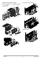
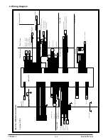
2. Wiring Diagram
1
2
4
5
6
7
8
9
10
11
12
13
14
15
16
GND1
+24V
GND1
+24V
GND1
CNA(B16B-PHDSS)
GND2
GND2
+5V
N.C.
TXD-FIN2
RXD-FIN2
+24V
DTR-FIN2/
DSR-FIN2/
RES-FIN2
FGS-FIN/
T1PF/
+5V
1
2
CNI(S3B-PH-K-S)
3
GND2
1
2
3
T1PF
3
STTM
15
17
19
14
13
11
2
1
T2OM/A
+24V
STUMB
STUMA
STTM-
4
3
22
SCRS/
+24V1
T2OM/B
16
STUM/B
STUM/A
+24V
+24V
N.C.
1
10
18
20
12
9
8
7
1
2
SCRS
6
5
21
+24V
N.C.
+24V
T2OMB
T2OMA
STTM+
+24V
2
CNC(B32B-PHDSS)
REAR Frame
+5V
EVM+
+24V
T2UP
T2PD
GND2
T2S/
5
6
4
3
2
1
11
7
8
9
10
12
13
14
EVM-
+5V
GND2
+5V
GND2
T2DN
Elevator UNIT
6
4
5
MME/
CND(B6B-PH-K-S)
MMCK
2
3
MMLK
1
GND1
2
3
1
4
5
MM
2
5
7
16
12
STSP/
13
4
1
STM-
STM-
8
3
10
14
STM+
9
CNE(B16B-PHDSS)
(STTD)
STM+
11
GND2
GND2
STHP/
STLS
STNC
STUHP
+5V
+5V
6
15
5
6
2
4
1
3
7
STM
8
9
10
11
12
13
STLS
STHP
STSP
STAPLER
4
6
8
COM1
7
2
PID/
FGS/
1
CNG(B9B-PH-K-S)
+24V
5
GND2
3
5
1
2
3
4
6
7
8
+24V
T2S/
+5V
T2UP
GND2
+5V
T2DN
GND2
+5V
T2PD
GND2
(SMP-18V-BC)
COM1
GND2
PID/
+24V
FGS/
Relay UNIT
SPS/
+24V
18
4
6
9
JFMB
19
8
15
7
2
1
13
11
20
14
10
17
12
16
5
+24V1
PPS/
3
21
22
23
24
+24V
JFM/B
JFM/A
JFMA
+24V
+24V
JRMB
JRM/B
JRM/A
JRMA
+24V
+24V
PSMB
PSM/B
PSM/A
PSMA
+24V
+24V
17
12
20
JFHP
18
6
4
16
2
SCPD/
13
9
PSHP
11
7
19
14
3
5
8
1
15
10
21
22
23
24
25
26
27
28
JRHP
COM2
SCID/
STTHP1/
PPD/
CNF(B24B-PHDSS)
CNH(B32B-PHDSS)
+5V
GND2
+5V
GND2
+5V
GND2
+5V
GND2
GND2
+5V
GND2
+5V
STTHP2/
GND2
COM3
GND2
+5V
GND2
SCID2/
29
30
31
32
PSM
1
2
3
4
5
6
JFM
1
2
3
4
5
6
JRM
1
2
3
4
5
6
FRONT Frame
STAPLE Compiler
3
JFHP
2
1
1
JRHP
3
2
1
3
2
PSHP
3
1
2
3
SCID
2
1
SCPD
STAPLER UNIT
To Option DCPS
Upper PG
FG
SMR-18V-N
(SMP-09V-BC)
STNC
GND2
+5V
DOPD/
FGS
DOPD
1
2
3
1
2
9
+5V
DOPD/
GND2
3
2
1
PID
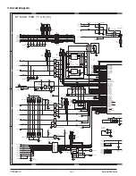
MAIN PWB TF
23
24
25
26
GND2
POD/
1
T2S
2
1
T2UP
2
3
1
T2DN
2
3
1
T2PD
2
3
SCID2
2
1
3
GY
OR
RD
RD
BL
PL
BR
PK
RD
RD
PL
BL
PK
BR
PL
BL
GY
GY
RD
GY
RD
GY
RD
BL
GY
OR
GY
OR
RD
BL
RD
BR
RD
BL
RD
BR
OR
GY
PK
OR
OR
GY
GY
PL
BR
RD
GY
BL
PL
BR
OR
GY
BL
OR
PL
GY
RD
BR
RD
RD
BL
PL
BR
PK
RD
RD
BL
PL
BR
PK
RD
RD
BL
PL
BR
PK
RD
RD
OR
GY
GY
GY
GY
GY
GY
GY
GY
GY
OR
OR
OR
OR
OR
OR
OR
OR
RD
RD
BL
PL
BR
PK
BL
BL
PL
BR
PK
BL
PL
OR
GY
BL
OR
PL
GY
RD
BR
RD
BL
BL
RD
GY
RD
BR
RD
RD
BR
OR
PK
GY
OR
PL
GY
OR
BR
GY
RD
BR
RD
BR
RD
RD
RD
RD
OR
YE
BR
BK
OR
YE
BR
OR
YE
BR
BK
BK
RD
1
3
2
POD
OR
GY
15
16
17
18
N.C.
N.C.
N.C.
GY
BR
(SMP-10V-BC)
1
2
3
5
6
7
8
9
10
+5V
+24V1
GND2
+24V2
4
STTHP1/
+5V
STTHP2/
GND2
+24V
PPS/
PL
PPS
1
3
RD
BR
DSW2
2
RD
RD
1
OR
3
1
GY
2
STTHP1
BL
GY
STTHP2
2
3
1
OR
PL
RD
1
PPD
3
2
BR
2
RD
1
SPS
SCGS/
1
BR
RD
SCGS
2
BR
RD
RD
S Paper Entry UNIT
OR
+24V
RXD-FIN2
TXD-FIN2
DSR-FIN2/
N.C.
DTR-FIN2/
+5V
GND2
GND2
GND1
+24V
GND1
+24V
GND1
2
+24V
5
13
15
FGS-FIN/
14
10
16
3
4
1
RES-FIN2
17
8
9
11
12
6
18
FG
7
N.C.
27
28
29
30
31
32
+5V
GND2
POD/
N.C.
N.C.
DSW1
2
1
3
RD
YE
2
BR
6
1
4
RD
OR
5
BK
STUM
EVM
2
1
+5V
BL
BL
FG
CNB(B6B-PH-K-R)
6
4
1
3
5
T2OM
2
1
2
3
4
5
6
GND2
+24V2
GND2
GND2
GND2
TEST
PL
BR
PK
GY
OR
BL
OR
PL
GY
STUHP
1
2
3
FG
GY
GY
SCID2/
GND2
COM3
(SMP-03V-BC)
1
2
3
9
FG
FG
+24V1
N.C.
N.C.
N.C.
FG
FG
GY
Left cover UNIT
GY
GY
BR
OR
BK
RD
WH
YE
GY
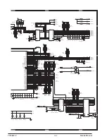
Tray 1 full detection
Compiler door SW
ST shift motor
Elevator motor
ST rotation motor
Roller pressure relief solenoid
Tray 2 solenoid
Tray 2 upper limit detection
Tray 2 lower limit
detection
Tray 2 paper detection
Tray 2 paper exit
detection
Tray 2 paper exit motor
Main motor
Elevator stay
Jogger F.H.P. detection
Jogger R.H.P. detection
Pusher H.P. detection
Compiler paper detection
Compiler paper entry detection
Compiler gate
solenoid
Compiler paper entry detection 2
Stopper solenoid
Staple replacement door SW
ST rotation detection 1
ST rotation detection 2
Paper hold solenoid
Jogger F motor
Jogger R motor
Pusher motor
Paper entry detection
Interface door open/close detection
Paper entry reverse gate solenoid
ST unit H.P. detection
Paper hold detection
1-D4
1-D2
A
A
B
B
C
C
D
D
E
E
4
4
3
3
2
2
1
1
AR-FN6 WIRING DIAGRAM
* "# $%&'()
Y105
620
-
2
Service Manual


