695 PROOFER
0695S20005
4-3
OPERATING INSTRUCTIONS – DIGITAL CONTROLS
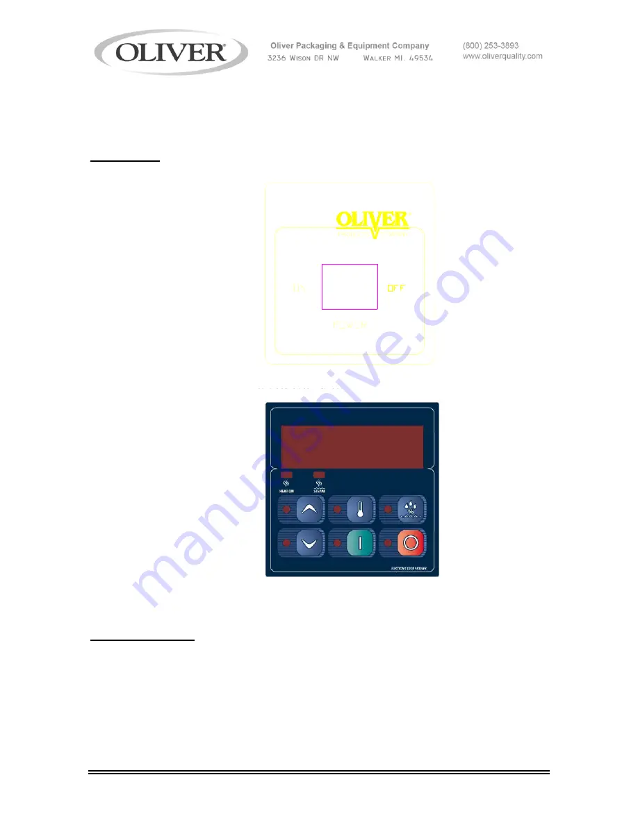
Control Panel
Figure 4.0
Beginning Operation
First turn the Proofer on using the power switch.
Proofer will start preheating to last set temperature and humidity. (
PrEH
will be displayed
until unit has reached temperature and RH settings then
REAdy
will be displayed –
Proofing can now be started
).
(continued)
Summary of Contents for 695
Page 20: ...695 PROOFER 0695S20009 8 1 ELECTRICAL PANEL MANUAL CONTROLS Revised 8 14 03...
Page 22: ...695 PROOFER 0695S20009 8 3 Revised 4 5 04...
Page 24: ...695 PROOFER 0695S20010 9 1 DOOR ASSEMBLY...
Page 26: ...695 PROOFER 0695S20011 10 1 HOUSING CHAMBER ASSEMBLY Revised 4 5 04...
Page 28: ...695 PROOFER 0695S20012 11 1 WATER SYSTEM ASSEMBLY...
Page 30: ...695 PROOFER 0695S20013 12 1 COVERS RACKS ASSEMBLY...
Page 32: ...695 PROOFER 0695S20014 13 1 115V WIRING DIAGRAM MANUAL CONTROLS 0695C12000 Revised 8 14 03...
Page 33: ...695 PROOFER 0695S20014 13 2 115V WIRING DIAGRAM DIGITAL CONTROLS 0695C12001 Revised 4 5 04...
Page 35: ...GEN020319 THIS PAGE WAS INTENTIONALLY LEFT BLANK...
Page 37: ...GEN020319 THIS PAGE WAS INTENTIONALLY LEFT BLANK...


