background image

1

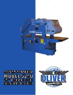
Oliver 5240 Owner’s Manual

Summary of Contents for 5240

Page 1: ...1 Oliver 5240 Owner s Manual...

Page 2: ...urchase OliverMachinerywillrepairorreplace atitsoption any component that fails under normal use Please note that the customer is responsible for returning the failed component to Oliver Machinery pre...

Page 3: ...r 12 5 1 Digital Controller Operation 13 5 1 1 Changing Units of Measure 14 5 1 2 Setting the Controller to a Specific Thickness 15 5 1 3 Calibrating the Digital Thickness Controller 16 5 2 Changing F...

Page 4: ...around the machine is well lighted 10 Utilize guards and other safety features whenever possible Keep all guards and safety features in good working order 11 Do not wear loose clothing neckties rings...

Page 5: ...Cutterhead Motor 20 HP Top Cutterhead Motor 15 HP Feed Motor 3 HP Table Height Motor 1 2 HP Maximum Stock Width 25 Maximum Stock Thickness 7 75 Minimum Stock Length 12 Feed Speed Variable 21 66 FPM K...

Page 6: ...signs of shipping damage If damage is found contact your dealer immediately For protection against shifting the double side jointing planer was bolted to the shipping pallet in four places see Figure...

Page 7: ...is level from front to back and left to right Note Even if your shop floor is level installation of the leveling feet will improve stability and reduce vibration A protective anti rust agent was appl...

Page 8: ...dust ports with hose clamps or similar devices 1 Attach a dust collection hose to the dust chute for the bottom cutterhead This chute is located at the lower right side of the machine as shown in Fig...

Page 9: ...e See Figure7 2 Openthedooroftheelectricalpanel Slidetheelectrical cable through the hole at the lower left side of the electrical box 3 Connect the 3 power wires at theterminalblock shown in Figure 8...

Page 10: ...ONTROLS This section is designed to be a quick overview of all the levers handwheels buttons etc on the Oliver 5240 double side jointing planer A general description of each item follows Figure 10 Det...

Page 11: ...pring loaded feed points of the feed system The entire bed of feed points can be moved up or down to decrease or increase the amount of pressure applied to the workpiece The orange lever is the lock l...

Page 12: ...ANER The following sections describe the steps to several common procedures performed when using the Oliver 5240 double side jointing planer These instructions are not meant to replace training by an...

Page 13: ...e Present Value PV Readout This LED readout displays the current thickness setting of the machine The readout currently displays a value of 31 3 Set Value Readout SV This LED readout displays the valu...

Page 14: ...ges will occur First the present value will change to uuuu Second the SET button indicatorlight will illuminate see Figure13 3 Now press the UNIT button once The present value shouldread2 17 andthe In...

Page 15: ...ssettingwillbedisplayedasthesetvalue For this example a thickness setting of 3 50 inches has been keyed into the controller see Figure 16 3 PresstheRUNbutton Thiswillcausethecarriagetomove up or down...

Page 16: ...theinfeedtabletozero sothatthebottomcutterhead does not remove any material 2 UsetheUPbuttononthecarriagecontrols ortheUPbut ton on the digital thickness controls to move the carriage to the highest p...

Page 17: ...ould display a value of 0 8410 13 Enter the measured thickness value from Step 11 on the keypad In our example the operator would enter 0 84 The value keyed in will be displayed as the SV Set Value Se...

Page 18: ...oximately 80 different feed speeds between 21 and 66 FPM There are two scales on this unit both are reference scales for feed speed The sidescaledisplaysvaluebetween0and10 Thefrontscaledis plays value...

Page 19: ...ant the final product to have a thickness of 1 Therefore we want the double planer to remove 1 4 of material For this example we will remove 1 8 from the bottom and 1 8 from the top of the board 1 Ent...

Page 20: ...th rounded corners Each square knife possesses 4 cutting edges so each cutter can be used 4 times before being replaced Note Oliver Machinery recommends that these insert knives NOT be re sharpened Th...

Page 21: ...nives 5 After rotating replacing all knives re install the dust chute from Step 2 and secure it with the two bolts 1 Beginbyopeningthedoorontherightsideofthedouble side jointing planer See Figure 30 2...

Page 22: ...Figure 34 8 Pull the cutterhead out to the side of the machine using the handle shown in Figure34 9 Oncethecutterheadispulledtothesideofthemachine the scene should look like Figure 35 10 Engagethecutt...

Page 23: ...hemachine Replacethe vee belts use the belt tension lever from Step 5 to re tension the vee belts 16 Tighten the lock bolt from Step 7 17 Replacethebeltcoverandlockitdownusingthelatches from Step 3 18...

Page 24: ...same height as the outfeed table The lower cutterhead height is set at the factory Should adjustment become necessary a measuring gage has been included with the machine see Figure 38 The height of th...

Page 25: ...ure Bar Adjustment Thebottomof thepressurebarshouldbesetapproximately 0 5mm below the lowest point of the upper cutterhead s cutting circle This is adjusted at the factory Should adjustment be necessa...

Page 26: ...lightweight chain oil such as Mobil Vactra Oil 2 X Check tension on upper and lower cutterhead vee belts X Lubricate oil cups on the left and right sides of the infeed bed ways with a lightweight chai...

Page 27: ...tate or replace all insert knives Feed speed too fast Reduce the feed speed Removing too much material Make two passes instead of one Material not feeding smoothly Dull knives Rotate or replace all in...

Page 28: ......

Page 29: ......

Page 30: ......

Page 31: ...le speed unit 1 15 H Flat Washer M10x 4 16 HA020733 Socket HD Bolt M12x55 4 17 DP010007 Key 1 18 DP010008 Chain Gear 1 19 HA030508 Set Screw M8x16 2 20 DP010009 Chain 1 21 DP010010 Joint 1 22 HC011900...

Page 32: ...sher M12 1 46 DP010021 V belt guard shaft 1 47 HC011200 Hexagon nut M12 1 48 H Flat Washer 34x 13x3 6 49 DP010022 V belt guard shaft 1 50 DP010023 V belt guard 1 51 DP010024 Cap HD Nut M12 2 52 DP0100...

Page 33: ......

Page 34: ...2 DP010029 Rear cover 1 3 HE021300 Spring washer M10 8 4 HA010616 Hex HD Bolt M10x30 8 5 DP010030 Motor 1 6 DP010031 Driven pulley 1 7 DP010032 Drive pulley 1 8 DP010033 Belt 1922V 376 1 9 DP010034 F...

Page 35: ......

Page 36: ...40 1 16 DP010046 Bush 1 17 DP010047 Pulley 1 18 HK025800 Belt A72 1 19 DP010048 Spacer 1 20 HE021300 Spring washer M10 1 21 HA020619 Socket HD Bolt M10x35 1 22 HE021500 Spring washer M12 4 23 HA020722...

Page 37: ...A090510 Flat HD SKT Bolt M8x20 5 44 HE021300 Spring washer M10 2 45 HC011000 Hexagon nut M10 2 46 DP010057 Ring 4 47 DP010058 Spring 2 48 HA010659 Hex HD Bolt M10x100 2 49 HE021500 Spring washer M12 2...

Page 38: ......

Page 39: ...064 Corrugated shaft 1 16 DP010065 Corrugated wheel 12 17 DP010066 Spring 72 18 DP010067 Spring needle 72 19 DP010068 Wheel holder right 1 20 DP010069 Wheel holder left 1 21 DP010070 Bearing Housing 2...

Page 40: ...38 HC010600 Hexagon nut M6 1 39 HA020413 Socket HD Bolt M6x25 1 40 DP010080 Spring 1 41 HA020413 Socket HD Bolt M6x25 1 42 HC010600 Hexagon nut M6 1 43 H Chain 1 44 H Chain joint 1...

Page 41: ......

Page 42: ...Socket HD Bolt M10x30 1 16 DP010086 Adjustment base Tension 1 17 HE021500 Spring washer M12 1 18 HC011200 Hexagon nut M12 1 19 DP010087 Adjustment lever 1 20 HC011200 Hexagon nut M12 1 21 DP010088 Ha...

Page 43: ...00 50 HA010637 Hex HD Bolt M10x65 100 51 DP010109 Bush 100 52 DP010110 Pin x plate 50 53 HC040800 Nylon Nut M8 100 54 HC041000 Nylon Nut M10 100 55 DP010111 Driven shaft 1 56 DP010112 Spike conveyor c...

Page 44: ......

Page 45: ...0121 Chain wheel 5 8 x41T 1 3 DP010122 Chain wheel 3 4 x37T 1 4 DP010123 Body 1 5 DP010124 Lining 2 6 DP010125 Bush 1 7 DP010126 Friction piece 1 8 DP010127 Disk spring 1 9 DP010128 Pressure adjustmen...

Page 46: ......

Page 47: ...rew 6 15 HC011000 Hexagon nut M10 6 16 HA010633 Hex HD Bolt M10x55 6 17 DP010138 Chain wheel 5 8 x20T 1 18 DP010139 Chain wheel 5 8 x20T 1 19 HH013515 Key 8x8x30 2 20 DP010140 Fixing piece 2 21 HE0213...

Page 48: ......

Page 49: ...t M8 2 18 HA030522 Set Screw M8x40 2 19 DP010161 Adjustment nut holder 1 20 HA020616 Socket HD Bolt M10x30 2 21 HC011000 Hexagon nut M10 2 22 HA030622 Set screw M10x40 2 23 DP010162 Elevation adjustme...

Page 50: ......

Page 51: ...Pulley 1 18 HK025200 Belt A66 1 19 DP010185 Fixing piece 1 20 HE021300 Spring washer M10 1 21 HA020619 Socket HD Bolt M10x35 1 22 DP010186 Spring 8 23 HA030721 Set screw M12x35 36 24 DP010187 Knife 4...

Page 52: ......

Page 53: ...P010201 Belt guard 1 19 HA020408 Socket HD Bolt M6x16 3 20 H Spring washer 19x 7x1 1 21 HE021500 Spring Washer M12 1 22 DP010202 Extend Shaft 1 23 HC012700 Hexagon Nut M27 1 24 DP010203 Shaft 1 25 HF0...

Page 54: ......

Page 55: ...washer M10 8 15 HA020628 Socket HD Bolt M10x50 8 16 DP010222 Dust guard bellow 4 17 DP010223 Elevation screw 2 18 H Key 7x7x25 4 19 DP010224 Spacer 4 20 HJ102900 Thrust bearing 2905 8 21 DP010225 Elev...

Page 56: ...010243 Touch bracket 1 51 HA040705 Round HD Phil Bolt M6x12 1 52 DP010244 Plate 1 53 DP010245 Flat HD Socket Bolt M6x12 2 54 DP010246 Tension adjustment base 1 55 HA030508 Set Screw M8x16 1 56 DP01024...

Page 57: ......

Page 58: ...ing ring S12 2 13 DP010263 Housing 1 14 HA020510 Socket HD Bolt M8x20 3 15 DP010264 Adjustment base 1 16 DP010265 Fixing piece 1 17 HE021300 Spring washer M10 1 18 HA020616 Socket HD Bolt M10x30 1 19...

Page 59: ...28 Oliver 5240 Owner s Manual 5240 Owner s Manual Rev 1 2 Oliver Machinery 1210 Andover Park East Tukwila WA 98188...

Reviews: